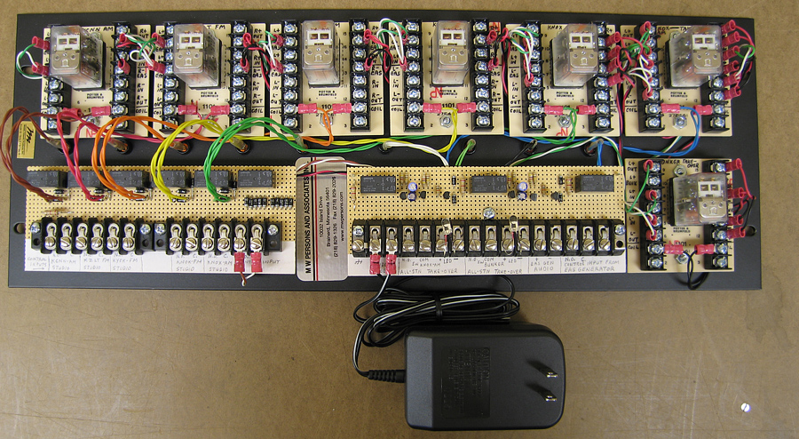
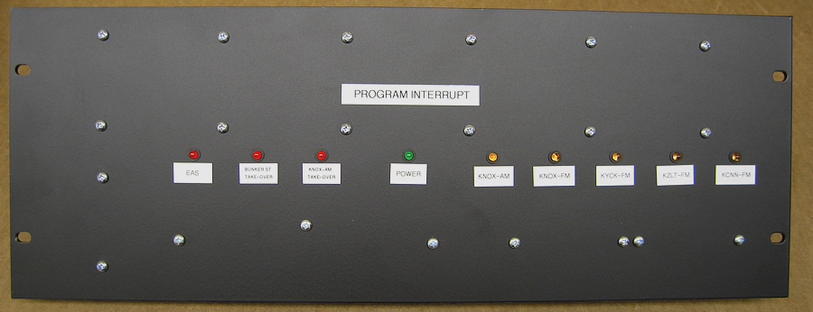
It is rare
nowadays to find a single-station operation. Even
in small markets I encounter groups of radio stations all under the
same studio roof. Most such groups
use a single EAS encoder/decoder unit with a relay system to
interrupt audio for announcements on all of the stations at that
location. I have built many audio relay panels for EAS systems to do
just that. It is not difficult.
A relay is used to interrupt normal audio for each radio station and
replace it with EAS audio. The relay
coils are controlled by an EAS generator. Just keep adding relays as
you add radio stations to a single EAS unit. They
can all fire simultaneously or one at a time if there are some
switches to limit the number of stations during a weekly or monthly
test.
 |
 |
An interesting twist comes when there is
a weather warning that is not covered by EAS and must get on the air
on all of the stations … probably simultaneously. If you have your
thinking cap on, you will realize that those same audio relays can
be used to do this job too. The difference is which audio source is
used to feed audio to those transmitters.
Loaded
A simple design modification will add a relay that either lets the
EAS system run its announcement or pulls in to take audio from one
“master control” studio and feed all transmitters. Key here are the
FCC rules that require EAS audio to take precedence over all other
station audio. The system must failsafe to EAS regardless
of what else is happening or what the program director might want to
happen in the facility.
One of the technical hurdles is that one audio source might be
required to feed six audio processors. If each of those processors
is set to terminate the incoming audio with 600 ohms impedance, you
could have a problem. A 600 ohm audio source will be loaded down to
100 ohms with a noticeable drop in audio level. Most audio
processors have a jumper option to select a “bridging” input, which
is usually 10,000 ohms. If you have
six 10,000 ohm loads in parallel, the resulting load is only 1667
ohms. It would take 17 such audio
processor loads to bring the combined parallel impedance down to 600
ohms.
For perspective, the 600 ohm standard is
from many years ago when audio consoles had output transformers that
needed a 600 ohm load in order to achieve good frequency response.
Active balanced circuits today do not need a load and are happy with
600 ohms or more of termination. For that matter, they perform just
as well with no load.
I remember installing an all-station take-over panel at a station a
while back. It was after 5 p.m. by the time the job was done. After
a look around, it became apparent that I was the only one left in a
building with six radio stations. There was a gleam in my eye.
Should I flip the switch and be heard by everyone in town? Hmmmm …
I’d always wanted to be an announcer on the radio!
Well, since radio waves travel at the speed of light, the
answer is probably halfway to Alpha Centauri by now.
 |
 |
Pencil and paper
Back to the subject at hand. My recommendation on custom-building an
interface panel is to draw a schematic diagram and keep it in the
station engineering records. You can
do it with pencil and paper as long as there is some kind of logical
information trail. That will help future engineers understand what
you have created. Do neat work and label everything. It just makes
good engineering sense.
There are those who do not have the time, skill, patience or tools
to construct such an interface. In
that situation,
I build
such devices in my shop and ship them out for engineers to
install. Yes, complete schematics are included.
The author wrote about
“Solving the Case of Tower vs. Tower” in the March 1 issue. For more
good ideas, visit radioworld.com
and click on the Tech Tips tab under News & Technology.


