 |
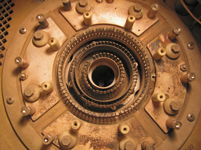
Here is
the socket with the screen contact ring removed. Something looks a
little funny on the left side of the right-hand screen bypass capacitor.
Click
on the photo for a larger view. |
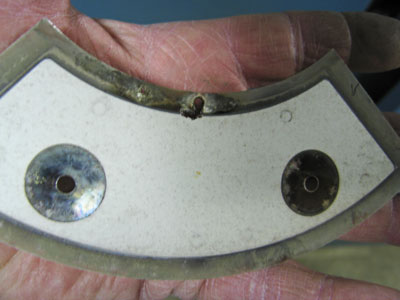 |
Sure
enough, the dielectric material has failed causing a short circuit in
the screen circuit. You can see the arc-through near the top.
Fortunately there was a spare part at the site.
In this transmitter repair adventure, that
screen bypass was not the only problem.
Click
on the photo for a larger view.
|
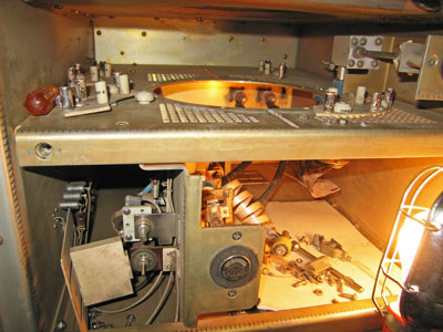 |
The
entire tube socket had to be removed for bench repair. Note the
scattering of parts in the bottom of the PA cabinet. A piece of
cardboard was placed over the incoming air duct to keep parts from
falling into the cooling fan.
Click
on the photo for a larger view. |
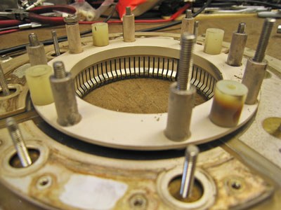 |
On the
bench, a nylon spacer was discovered as the cause to why control grid
voltage went to near zero at times causing sudden PA overloads.
You can see it discolored brown and black on the right side of the
socket. Since those are no longer readily available, I used a
porcelain insulator as a replacement.
Click on the photo for a
larger view.
|
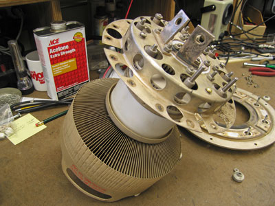 |
After
the spacer was replaced, the tube socket needed to be reassembled.
It is extremely important to get the socket contact rings aligned
properly. Failure to do so could cause undue physical stress on
the tube causing an air leak at one of the seals and tube failure.
The best way to get
the alignment right is to use a tube. Tighten the hardware as much
as possible, then remove the tube and do the final tightening.
Recheck to make sure the tube fits easily into the socket.
Click
on the photo for a larger view.
|
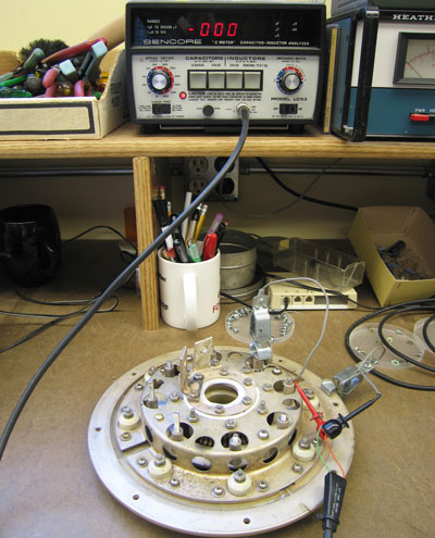 |
Here the
socket insulators and bypass capacitors are being tested with a Sencore
Z Meter to see if there is any leakage at 600 Volts.
Click on
the photo for a larger view.
|
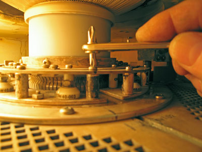 |
Back in
the transmitter, the screen ring had to be installed and tightened after
the rest of the socket was in place. Again, the tube was used as a
jig to get the alignment right. Also, you can never have too many
tools. A right-angle screwdriver with ratchet was ideal for final
assembly.
Note the black line on
the socket and transmitter cavity. That helped get parts back in
the original orientation. You can get into real trouble in a hurry
if you don't think it all through first and mark the way as you go.
This kind of project
is not for the faint of heart.
Story from October
2009 at KMFY Radio in Grand Rapids, MN.
Click
on the photo for a larger view.
|
