 |
|
|
|
|
||||||||||
|
|
|
||||||||||
|
Technical
Tips from Mark W. Persons |
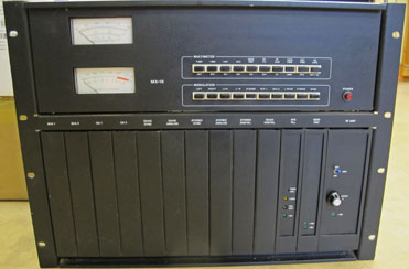 |
The
Harris MS-15 and MX-15 series of FM exciters dates back to about 1980.
They were designed to accommodate built-in audio processing, which was
an idea that didn't pan out out for Harris. Regardless, these
exciters worked well and are still serving the industry after all these
years. Here is the story of one such exciter in service at a Minnesota station: |
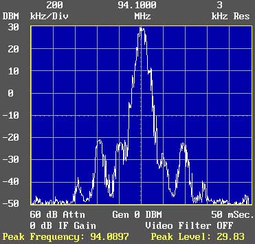 |
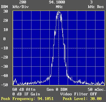
This
is a spectrum analyzer view of an FM radio station on 94.1 MHz. I
looked at the station after being alerted by the manager that the station was
being heard on no less than seven spots on the radio dial. Sure enough,
there was unwanted radiation on 93.5 MHz, 93.7 MHz, 93.9 MHz, 94.3 MHz, 94.5
MHz, and 94.7 MHz.
The IFR A-7550 Spectrum Analyzer told the gruesome story. Now...what to do about it!!!
|
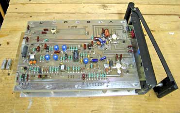 |
The first place I go looking for unwanted
spurious radiation is the FM exciter. In this case, it was a
16-year-old Harris MX-15. It seems just like yesterday when I
installed it new. This photo shows the exciter's 15-watt RF Power
Amplifier, Harris number 992-6204-001.
Electrolytic capacitors C8 and C18 needed to be replaced. The original capacitors were Sprague 30D TE1305 20 MFD/50 VDC. The bad pair are shown to the left of the module on the service bench. They are silver in color and I have seen this type of capacitor fail before. The replacement capacitors are in the module and difficult to see. They are blue in color and to the right side just above and below center on the module. |
 |
Success!!! The station is now heard on just one spot on the FM dial. The station manager and I laughed about whether this was the right thing to do or not because they need all the listeners they can get. |
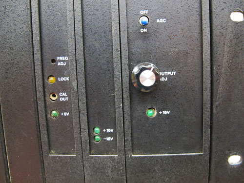 |
But
wait, there's more!
Here is a valuable update to the exciter. It is an RF power control with a knob replacing the trimpot that was in that same location before. It is common to see the trimpots broken from frequent adjustments and by pushing too hard on the control with a screwdriver. This modification solves that problem. It is not a factory update, but something I have done many times in the shop. |
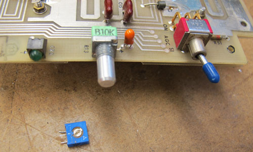 |
Here is
the control pot in place on the RF power amplifier board.
The original blue-colored trimpot is seen lying on the bench. |
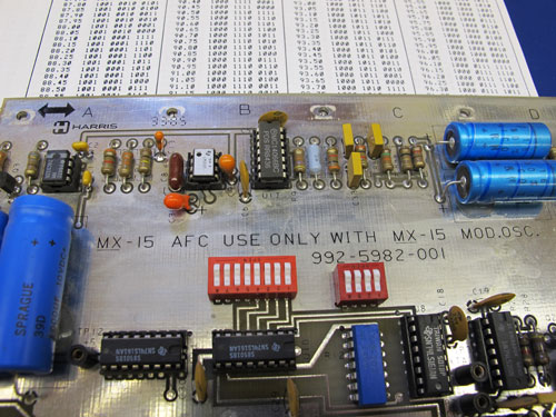 |
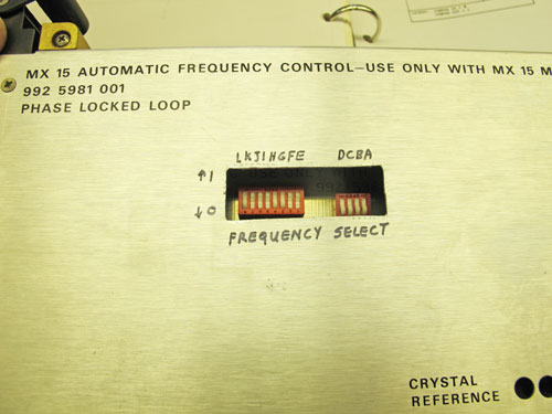
Another
valuable modification is to make the exciter easily frequency
programmable.
To do that, I replace the original frequency-select wire jumpers on the AFC (automatic frequency control) card card with dip-switches. They are the red and white switches in the center of this photo. |
 |
I also
cut a hole in the AFC module cover so the DIP switches can be easily
moved to change frequency. There are sheets in the Harris
equipment manual telling users the correct wire jumper and now switch
settings for each desired frequency. You can see a portion of
those sheets in the top of the photo above.
A frequency agile exciter makes a lot of sense in today's world. It is easy to do with easy access to the DIP switches. |
|
The stories go on and on.
Stop in again sometime. I'll leave the soldering iron on for you.
|
|
Questions? Email Mark Persons: teki@mwpersons.com |