 |
|
|
|
|
||||||||||
|
|
|
||||||||||
|
Technical
Tips from Mark W. Persons |
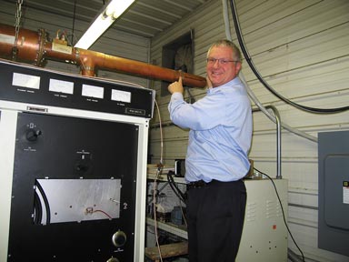 |
March 4, 2008: Here is your intrepid engineer Mark Persons adjusting the second-harmonic trap on the output of a Harris FM-20K Transmitter at KMSU Radio in Mankato, MN. The exact length of this trap gives the best harmonic suppression. An adjustment needed to be made as a part of tuning the transmitter to a new frequency. Mark remembers installing two Harris FM20K Transmitters in a combined arrangement for 40 KW output at WTBX Radio in Hibbing, Minnesota. He got them on the air on New Years Eve, 1980. |
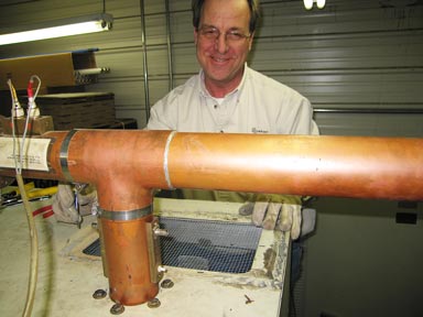 |
Marv Olson was working on this project at the same time. He is wearing gloves and just got done replacing an air screen above the power amplifier cavity on the top of the transmitter. The screen is 1/4" hardware cloth. It is not uncommon for these screens to be accidentally broken or burned from high RF inside the cavity. Best to check the screen on a regular basis to make sure it is fully intact. |
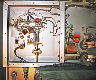 |
This photo is looking straight up at the driver stage of the transmitter. You can see two sockets for 4CX250B tubes. To the left of the left socket is a black mark. A 500 pf/500 Volt bypass capacitor has failed causing instability in the transmitter. Each socket has four of these capacitors. One has already been replaced by a 470 pf/3 KV capacitor. You can see it in yellow on the 2 O'clock position of the left tube socket. |
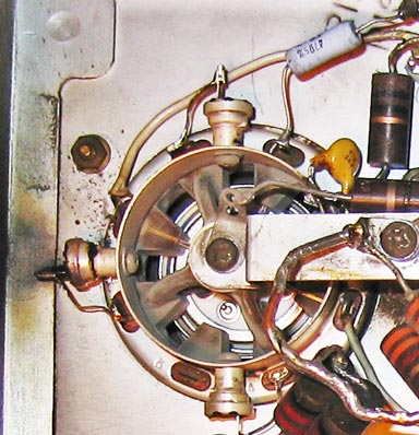 |
Here is a closer view. I make it a habit nowadays to replace all of these old capacitors when I find one has failed. The higher voltage is a good idea because an arc-over in one of the tubes from screen to plate could easily cause the failure of one of the 500 Volt capacitors. With 2000 Volts on the plate, the 3000 Volt capacitor is unlikely to fail. By the way, soldering on the underside of the driver is a difficult experience. Plan on spending at least an hour doing the capacitor replacement. |
|
|
If you wind up tuning the transmitter for 10 KW or less, you will probably want to rewire the high-voltage power transformer to WYE instead of delta on the 208/240 VAC input. To do that, you need to join one end of each primary winding with jumpers as shown to the left. This transformer is not the original Harris issue, but is a Peter W. Dahl transformer so yours might look a little different. When you get done, the PA voltage will be in the 5000 to 5600 VDC range instead of the 9000 VDC that you might have had otherwise. |
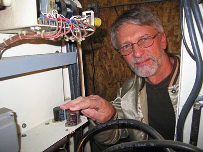 |
Here is Scott Schmeling, Chief Engineer for the Linder stations in Southern, MN. He is showing us two the new 220 MFD/400 VDC capacitors that he just finished installing in the bias power supply. The capacitors came with mounting plates making them a direct replacement for the original 150 MFD/450 VDC capacitors. The power supply makes bias for the IPA and PA stages. |
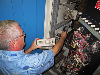 |
After replacing the
capacitors, it was necessary to measure and adjust the bias voltages with the
filament and bias voltage power supplies on, but the high voltage turned off.
There are controls for each of the two voltages involved. That is your handsome, but turning grey haired engineer, Mark Persons, doing the work. |
|
The stories go on and on.
Stop in again sometime. I'll leave the soldering iron on for you.
|
|
Questions? Email Mark Persons: teki@mwpersons.com |