 |
|
|
|
|
||||||||||
|
|
|
||||||||||
|
Technical Tips from Mark W. Persons |
|
Harris 700 Watt Preamplifier Modification |
 |
|
August 29, 2015: This is a
Harris
740-111-0000 IPA module,
often used in Harris HT 25FM, HT 30 FM, and HT 35FM Transmitters.
You normally see it with a blue cover over the electronics. Its
job is to make as much as 700
watts to feed the transmitter's tube. As you can see, at
least two 2-watt carbon
composition resistors overheated and failed. I have seen this
before and the cure was to replace the resistors with larger ones
allowing
the amplifier came back to life. Not this time. Coaxial
cable matching lines caught fire when touching the cabinet resulting in
transistor failure. That transistor is no longer available. |
 |
|
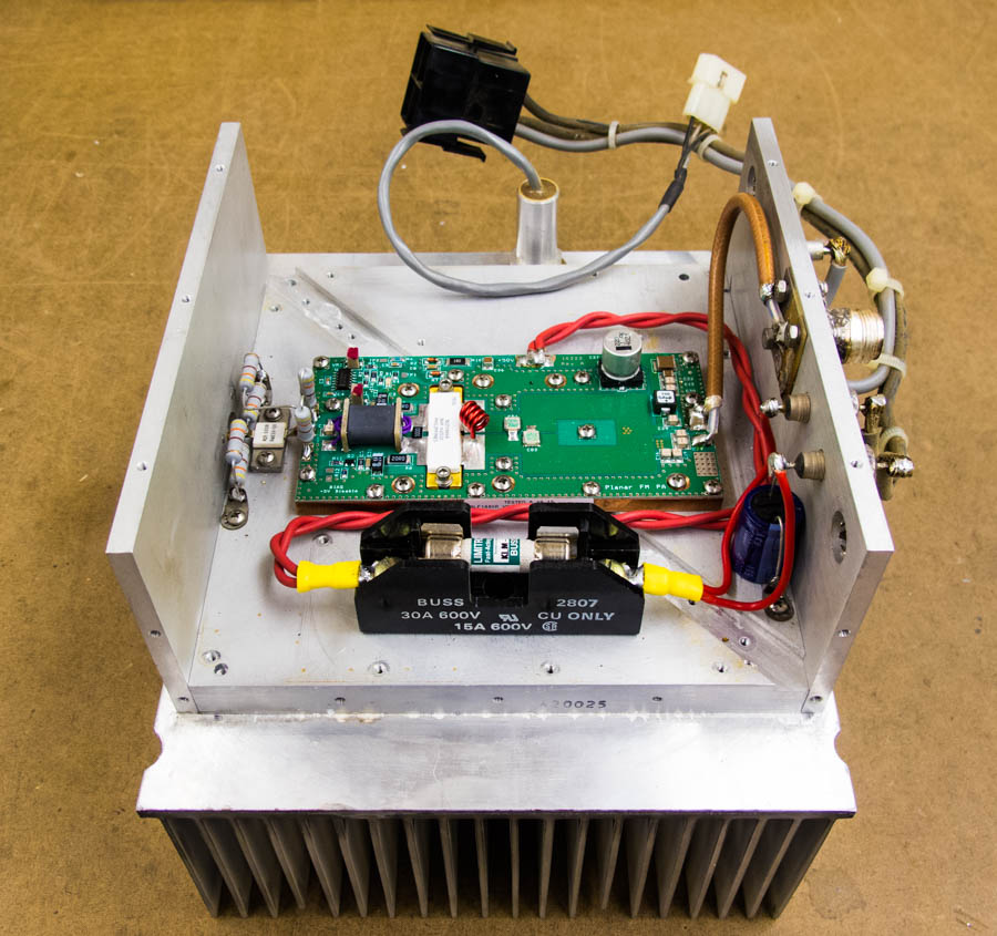
This is a the revised 700 Watt Intermediate Power Amplifier. It
uses a
Broadcast Concepts BLF188XR Planar 1000 watt pallet amplifier.
The amplifier can be
used to achieve 700 watts of output RF power when the incoming power is
48 VDC. The pallet amplifier is designed for 1000 watts, but the
transmitter's power supply is only capable of running it at 700 watts.
Actually, they normally run between 400 and 500 watts to achieve normal
transmitter output power. |
 |
|
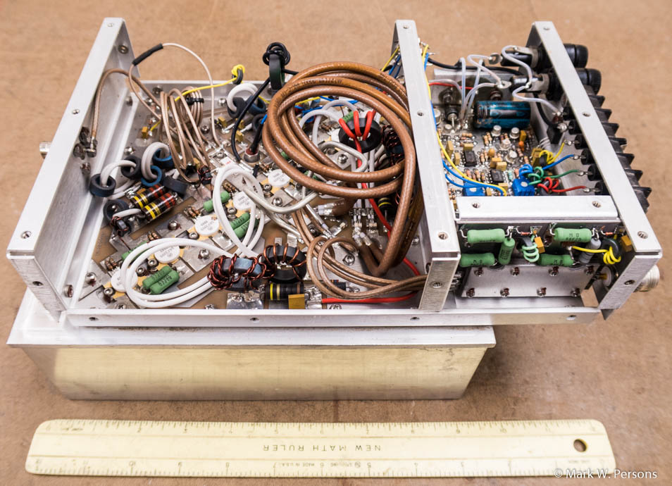
March 1, 2017:
Here is a different version of the 700 watt amplifier.
There is a control board to shut down the amplifier if there is
excessive reflected power or if the temperature goes too high. |
 |
| This is the amplifier with a new Broadcast Concepts BLF188XR 1000 Watt Planar Pallet Amplifier installed. The original aluminum chassis has been cut away so the new pallet can sit directly on the heat sink for best cooling. Note: Customers should not run this amplifier at 1000 watts because the transmitter's power supply is only capable of supporting a 700 watt amplifier. They normally run at about 400 watts with only 10 watts of RF drive. Below the amplifier, in the photo, is a shorted quarter wave stub trap to protect the amplifier when there is an arc-over in the tube it is driving. The T adapter on the stub goes to the amplifier output. A line to the transmitter power amplifier connects to it as well. |
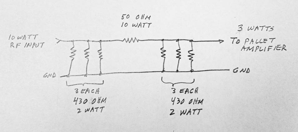 |
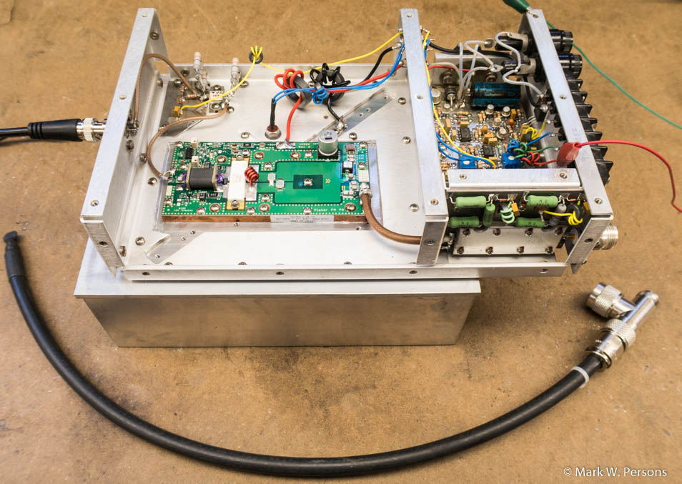
| The diagram above shows low-inductance resistors that were added on the input side to reduce 10 watts of exciter RF power to about 3 watts. |
|
The stories go on and on.
Stop in again sometime. I'll leave the soldering iron on for you.
|
|
Questions? Email Mark Persons: teki@mwpersons.com |