![]() |
|||||||||||||
|
Radio
Broadcast Technical Consulting and Sales |
||||||||||||
|
|
|
||||||||||||
|
Technical Tips from Mark W. Persons |
|
For Collins/Continental FM Transmitters |
![]() |
This is a honeycomb
air filter from a Collins/Continental 20 KW FM transmitter. The
filter was between the PA blower motor and the IPA compartment, just
below the PA tube socket. It is mostly clogged with dirt and needed
to be cleaned after just six years of service. 
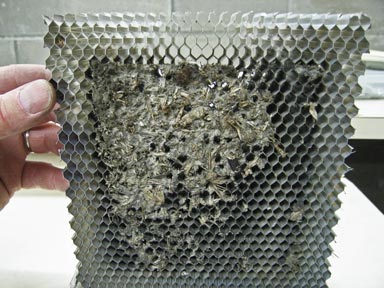
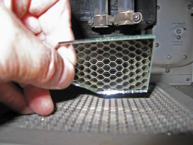
This kind of obstruction will easily raise the temperature of the tube and reduce its life. Best to check and clean as often as possible. |
![]() |
That honeycomb filter is shown here and it looks just fine from the top side. |
![]() |
Use a mirror and
flashlight to see through the honeycomb filter. This photo shows a
clean filter. 
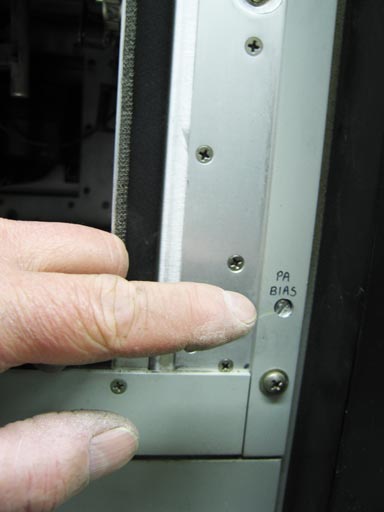
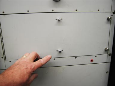
In the back right, you can see where the PA Bias control was until the transmitter was modified. This is a very inconvenient location and it cannot be adjusted while the transmitter is on the air. |
![]() |
I modify these transmitters so the PA Bias control can be adjusted from the front, near the lower-right corner of the IPA compartment. What you see is the end of a 1/4" metal extender shaft on the rheostat, which has been moved outside the IPA compartment. What a great thing it is to be able to adjust this control while the transmitter is on the air. |
![]() |
Here is the control, on an aluminum plate just before clean-up work was done from where it had attracted dirt in its previous location. |
![]() |
On the bottom left front of the transmitter is the overload relay panel. In case this one does not look like your panel, it has been modified with new overload relays from Continental. These relays plug into relay socket cards, which need to be mounted in the chassis in place of the original relays. The small problem is that the new relay socket cards are larger than the original relays so one of the relays needs to go above the left-most one. Correspondingly, wires needed to be extended to make it all work right. The 1-1/2 hour effort was worth it though. Problems of vibrations shutting the transmitter off are no longer the case. |
![]() |
The older
Collins/Continental
transmitters also have selenium diodes
(VR1) on the high voltage power supply and (VR2) on the screen voltage
power supply. They are
known in the parts manual as
"Absorber, Overvoltage."
More specifically, the selenium
stacks are wired across filter reactors.
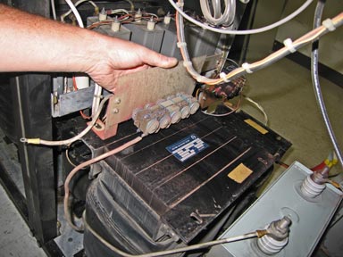
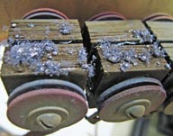
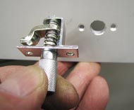
The left photo shows a bad one being removed from the high voltage reactor. The right photo is a close-up of some of the failed devices. Continental has deleted these selenium stacks from current designs because, as we heard, they were not needed and turned out to be more trouble than they are worth. |
![]() |
The older transmitters also did not have latches in the center of the IPA door. The door could warp allowing RF to leak past the RF gasket seal on the door. Continental added smaller latches half-way across the door on the top and bottom to give good pressure on the gasket. Older transmitters can be retrofitted with latches, purchased from Continental. |
![]() |
![]() |
On the left is a latch that is about to be installed in an IPA door. The right photo shows the latch from inside the door. Flat-head 4-40 screws were used to secure the latch to the door. |
|
The stories go on and on.
Stop in again sometime. I'll leave the soldering iron on for you.
|
page last edited 11/27/2008