 |
|
|
|
|
||||||||||
|
|
|
||||||||||
|
Technical Tips from Mark W. Persons |
|
Continental 802B FM Exciter |
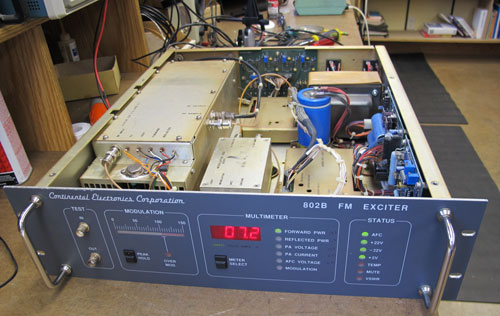 |
Here is a Continental Electronics 802B FM Exciter on a service bench. The unit is capable of producing 50 Watts of output power on any frequency from 88 to 108 MHz. |
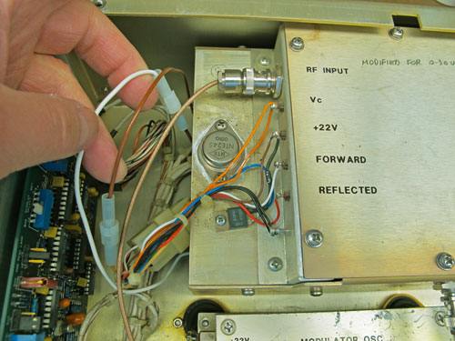 |
This
exciter was in a shop to replace the series-pass transistor in the PA
(Power Amplifier) power supply. Shown here near the end of the PA
heat sink assembly, it is an NTE245 NPN Darlington transistor.
That transistor is a TIP142 or an SJ3001 on some models. Those
transistors can fail because they heat-up as they regulate the 3
to 28 Volts DC PA power supply at up to
4 amperes of current. There is a Continental factory recommended modification (200230-1) to increase the reliability of the transistor by keeping it cooler. To do that, a 4 ohm/100 watt resistor is installed under the heat sink. Wiring is modified with quick couplers, shown here on white and brown wires, to connect or disconnect the resistor in series with the input to the transistor. When connected, the exciter is capable of producing only 30 watts of RF power. As it turns out, the transistor produces its most heat when operating the exciter at under 30 watts of power so it shares the heat with the resistor when connected. |
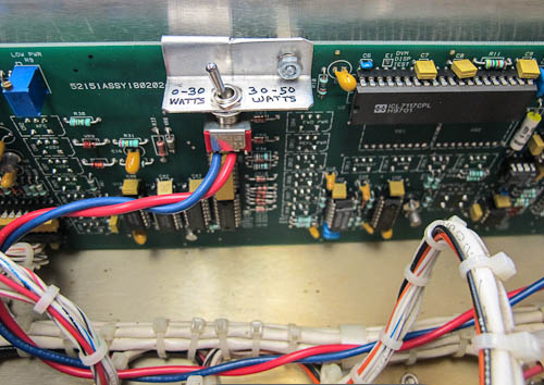 |
A switch can be added behind the front panel
to engage or disengage the resistor. Easy enough to do. |
|
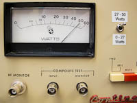 |
This same fix can and should be done to the Continental 802A FM Exciter. In this case, the switch is on the front panel. | |
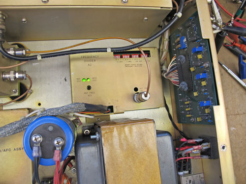 |
Another potential problem with this,
and many other exciters, is with dip switches, which are used to program the
exciter's operating frequency. They are located in the Audio/AFC
(Automatic Frequency Control) module shown in the center of this photo. This particular FM exciter developed an interesting problem. Its RF output would drop to zero for a few seconds and then come back up to normal, except it was 2 MHz higher in frequency. The trouble was caused by an intermittent contact on one of the dip switches. Later, it would do the same thing and come back on the correct frequency. Rule of thumb: If the dip switches are over 20 years old, just replace them to avoid problems. |
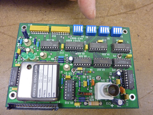 |
Here is
a better look of the Audio/AFC circuit card. The dip switches for
programming the operating frequency are on the upper right side of the
card. There is a 10 MHz reference oscillator on the lower left
side of the card, which is divided down in frequency and compared with a
sample of the modulated oscillator, which is also divided down.
(Story from April 16, 2011) |
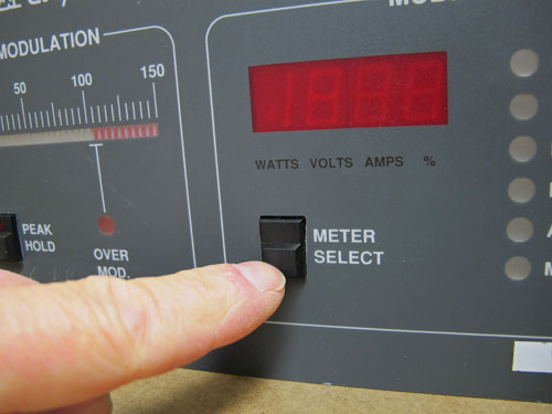 |
Some users of the
802B FM Exciter have reported that pushbuttons on the front panel will
stick so they do not push in or release as anticipated. The
solution is to remove the front panel from the mainframe of the exciter.
Then remove the circuit card on the back of the front panel. Use a
file to slightly enlarge the holes where the switches protrude through
the panel. Finally, reassemble it all.
(item from 12/11) |
 |
 |
| The
internal modulated oscillator is suspended above the bottom plate of the
exciter on rubber mounts. Shipping the exciter can cause the
oscillator module to break loose from the mounts and cause havoc on
other components inside the exciter chassis. One solution is to
drill a 1/4" diameter hole in the oscillator base and install a 4-40
machine screw in the chassis. Cover it with heat shrink tubing.
Under normal circumstances, the screw will not touch the oscillator.
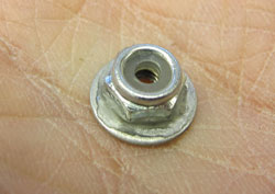
A 4-40 lock nut with washer glued to it should be installed on the 4-40
screw to keep the modulated oscillator in place during shipping.
Leave about a 1/16" gap so the nut is not touching under normal
circumstances. If you do it right, the oscillator can still float
free on the rubber shock mounts, but is held in place to prevent
disaster during shipping.
This modulated oscillator, like any FM modulated oscillator, is susceptible to chassis vibration causing artifacts in the air sound of the station. The effect is known as "microphonics." You can hear this in station audio if you tap on the modulated oscillator with a screwdriver while listening to a radio tuned to that frequency. All is well until an earthquake strikes. Listeners may hear the oscillator module hitting the 4-40 screw and nut. It is a small price to pay to prevent engineering problems! |
|
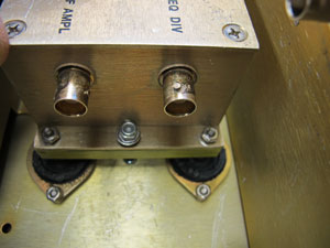 |
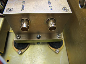
Here is a
photo of the lock nut in place. The entire procedure takes less
than an hour and is well worth the results. (oscillator Item from 12/11) |
|
The stories go on and on.
Stop in again sometime. I'll leave the soldering iron on for you.
|
|
Questions? Email Mark Persons: teki@mwpersons.com |