 |
|
|
|
|
||||||||||
|
|
|
||||||||||
|
Technical
Tips from Mark W. Persons |
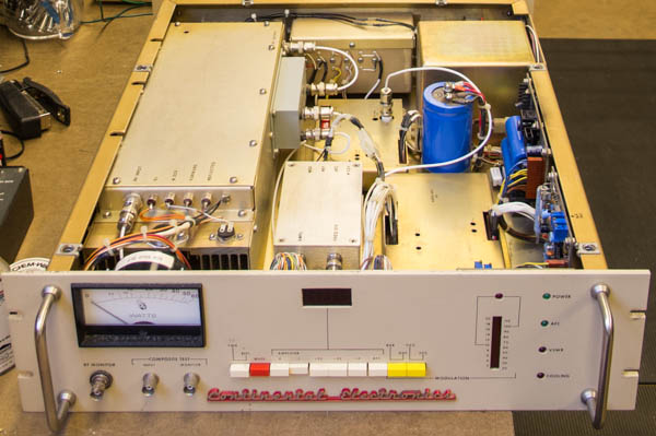 Continental 802A FM exciter |
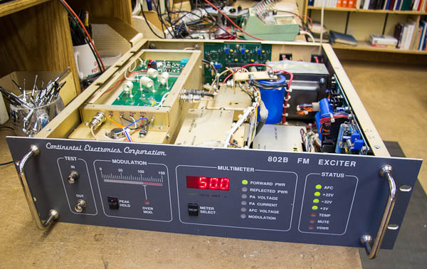 Continental 802B FM Exciter |
|
If you have one of these exciters, then the factory recommends you
install a kit to cut down on the heat load experienced by a series
regulator transistor for the RF power amplifier. Continental
bulletin 200230-1 shows a 4 ohm/100 watt resistor connected in series
with the voltage regulator. We typically use two 2 ohm/50 watt or
two 3.3 ohm/50 watt resistors in series. They mount on the power
amplifier module sides next to the heat sink where they get plenty of
cooling from the fan. |
|
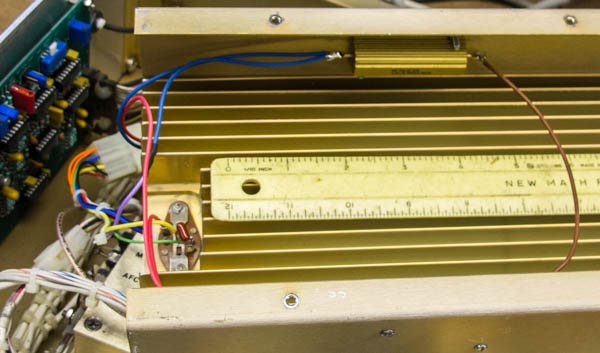
A ruler is lying on the heat sink so you can get a sense of size. |
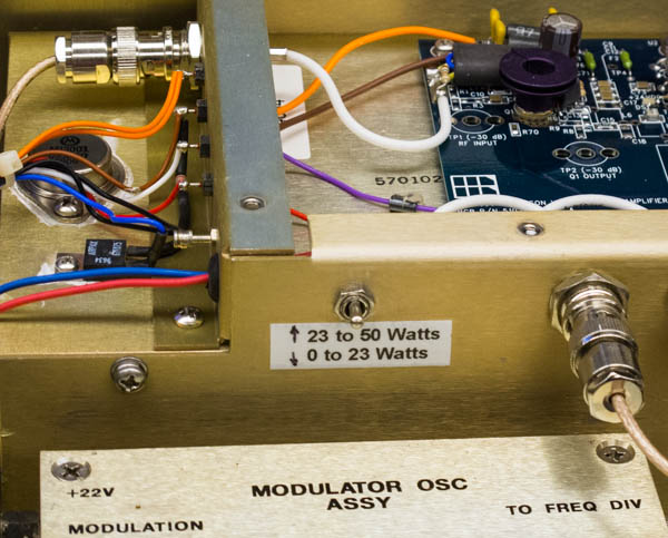
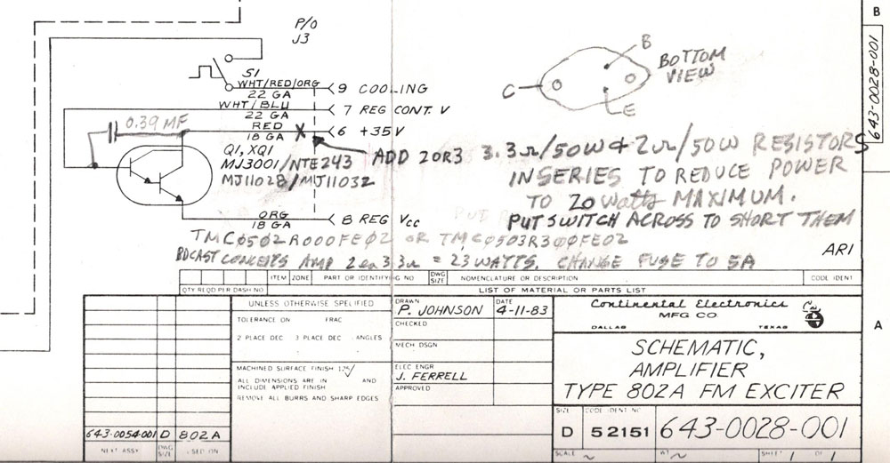
The low power switch position, in this case 0 to 23 Watts, enables the two resistors to dissipate much of the heat that the regulator transistor would have. That transistor can be seen on the left as a metal diamond-shaped device mounted to the heat sink. Without this modification, the transistor runs hot and has a high failure rate especially when exciters are set to between 10 and 20 watts of RF output. Below is a hand-modified schematic showing the modification. The actual low power maximum output power will vary depending on the RF transistor in the amplifier. Add more resistance to lower the power or reduce the resistance to raise power. |
 |
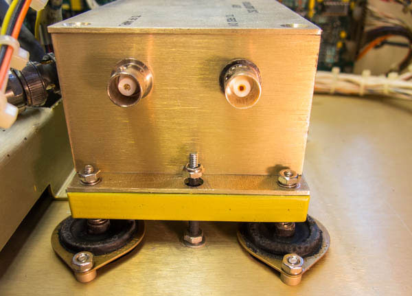
This will prevent the modulated oscillator from breaking loose while it is in transit, which could cause damage to the oscillator and other circuits in the exciter. If you carefully drill the holes and move the bolts around in the holes, you can get it so the extra 4-40 screw does not touch the modulated oscillator when it is running. |
|
The stories go on and on.
Stop in again sometime. I'll leave the soldering iron on for you.
|
|
Questions? Email Mark Persons: teki@mwpersons.com |