 |
|
|
|
|
|
||||||||||
|
Technical
Tips from Mark W. Persons |
 |
|
|
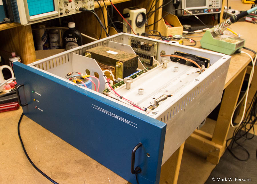
Many will recognize this as a 250 watt FM IPA amplifier from a
Broadcast Electronics B series 1.5, 3.5, 5, 10, 20, 25, 30, and 35 KW FM
transmitter. Later production runs have a beige color.
It is used to drive a tube power amplifier. Shipping can be
hazardous. The 31 lb. power transformer might come loose and flop
around after securing bolts pull through the aluminum chassis. All
it takes is being dropped during shipping. The other part is the
fact that the tapered mounting holes, for flat-head 1/4-20 bolts, were
bored too far into the aluminum. They were deeper than just plain
flush. That can leave them unable to hold the transformer during
rough handling. Best to bore new holes nearby that are not
as deep and can actually leave the bolt heads sticking slightly through
the aluminum bottom of the assembly. |
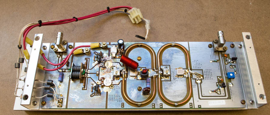 |
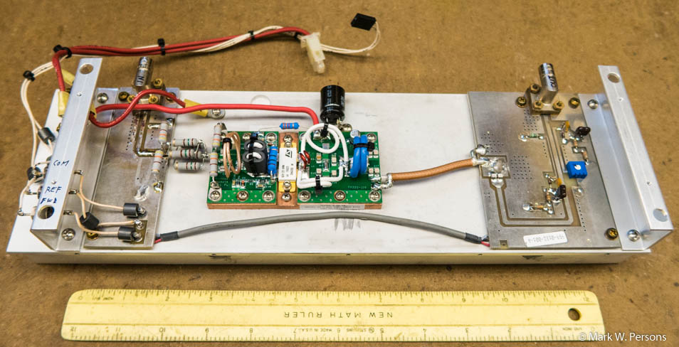
| Here is the RF amplifier assembly where the
top of the uppermost RF power transistor is missing. It blew off
when the transistor failed. They are SD1460 or MS1281A NPN planar VHF transistors that are difficult to get.
The circuit board is damaged too. Ouch!
June 2016: Broadcast Electronics
says it will not sell transistors to the end user, but will instead
repair modules in their facility for about $850, depending on how much
work needs to be done. A complete amplifier chassis swap can
be purchased for $1592. |
 |
 |
|
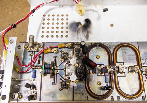
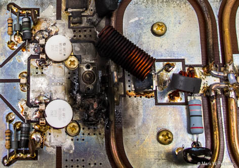
This RF amplifier was damaged by lightning. Serious
trouble....not repairable by just replacing transistors.
|
|
 |
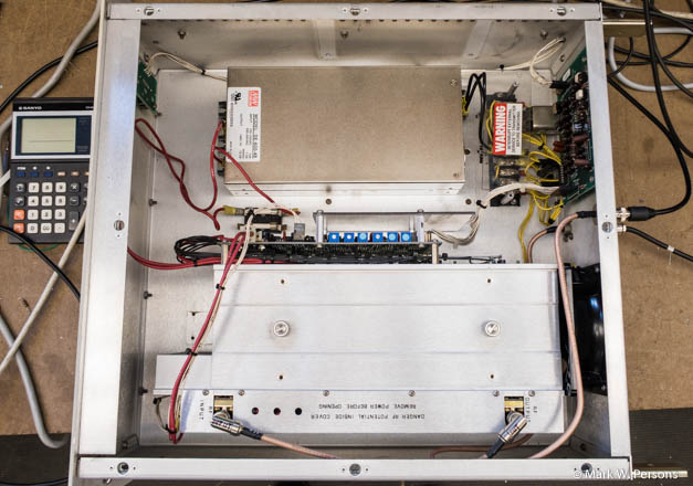
| Here is a
Broadcast
Concepts SD2942/FM350 Pallet
Amplifier installed in place of the original amplifier. RF input to the new pallet has nine resistors, which form an RF pad on the left. The pad is two 430 ohm/2 watt resistors to ground, then five 150 ohm/2 watt resistors in parallel, then two 430 ohm/2 watt resistors to ground. It takes about 9 watts of RF drive to get the refurbished amplifier to full power. |
 |
 |
|
Repairs and modifications give up to 150
watts of RF output for BE 1.5, 3, and 5 KW B
series transmitters.
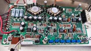
It takes 48 volts to get a full 350 watts from this amplifier design. To make the modification work, a good choice is to replace the original power supply with a 48 VDC/600 watt switching power supply and substitute the 120 VAC cooling fan with one that requires 240 VAC. The unit then runs only on 240 VAC, unless other modifications are made. The amplifier's DC controller card needs to be included in the final design. That card turns DC on only after the transmitter's tube has high voltage. Also it regulates DC voltage to the amplifier, and cuts the IPA power back in case of high VSWR. In the end, the pallet amplifier only gets 42 volts under normal operating conditions, but easily makes 250 watts. |
|
Warning!! You should not do this modification if the IPA amplifier is to be combined with another existing Broadcast Electronics RF amplifier as there is likely a phase difference, which will not work well when the two are brought together in a combiner. Amplifiers need to be very similar in characteristics in order to add power together in a hybrid combiner to feed the tube. |
|
August 26, 2013 email: Just read your latest pallet amplifier install in the BE IPA. Very nice job as usual. I'd say you've got this kind of repair/rebuild down to a science. Bob in Hamden Connecticut. |
|
The stories go on and on.
Stop in again sometime. I'll leave the soldering iron on for you.
|
|
Questions? Email Mark Persons: teki@mwpersons.com |
.