 |
|
|
|
|
||||||||||
|
|
|
||||||||||
|
Technical
Tips from Mark W. Persons |
 |
|
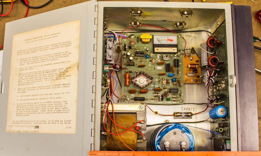
Some might recognize this
as an LPB 20 watt AM transmitter. It is my understanding that LPB
is out of business so it it up to others to keep this equipment
running. A ruler across the bottom shows the unit is about 11-1/2
inches wide.
If you look closely, the RF oscillator crystal has been removed, along with two integrated circuits in the oscillator circuit. The original design started with a crystal at 6 times the transmitter's operating frequency and divided it down. The unit you see here must have been an early version as there was no adjustment to set the crystal to within +/- 20 Hz of the required frequency to satisfy FCC rules. This one was about 200 Hz off frequency when tested in a shop. Since the transmitter needed to go to a new frequency, a fundamental on-channel crystal was used. In this case it was 1560 KHz. A new oscillator board is to the right of the meter and is orange/brown in color. There is an FET RF oscillator, followed by a transistor buffer amplifier stage, to drive the modulator in the transmitter. It all worked out very well. In many cases, the RF
output low-pass filter network will need to be modified when
moving to a new frequency. The plan here is to use a return loss
bridge to tweak component values, in the output tuning network, so the
RF amplifier sees 50 ohms with little or no reactance at the carrier
frequency. Changes in the RF output network could result in less
than normal RF harmonic attenuation. So, check RF harmonics to
verify they are within FCC specifications. |
 |
 |
| One
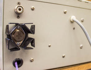
known problem with these units is the 28 VDC regulated power supply.
The original Darlington regulator transistor was a 2N6043, which was
later replaced with a 2N6388.
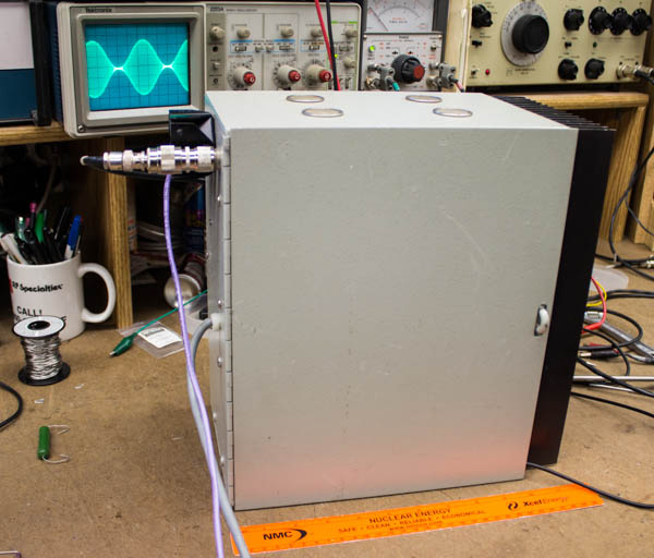
Another answer is to replace the transistor with an MJ11028 or an MJ11032. These have TO-3 cases for greater heat dissipation. In this case, a heat sink was added to further cool the regulator. No matter how you look at it, this transmitter needs plenty of cooling. It draws 135 watts from the 120 VAC power line to produce 20 watts to the antenna output. The unit needs to be wall mounted with the PA heat sink vertical so air can flow through it. Air cooling also applies to the voltage regulator. You don't need a cooling fan for the unit, but it does need plenty of room for convection air cooling. An air conditioned building helps too.
|
|
The stories go on and on.
Stop in again sometime. I'll leave the soldering iron on for you.
|
|
Questions? Email Mark Persons: teki@mwpersons.com |