 |
|
|
|
|||||||||
|
|
|
||||||||
|
Technical
Tips from Mark W. Persons |
 |
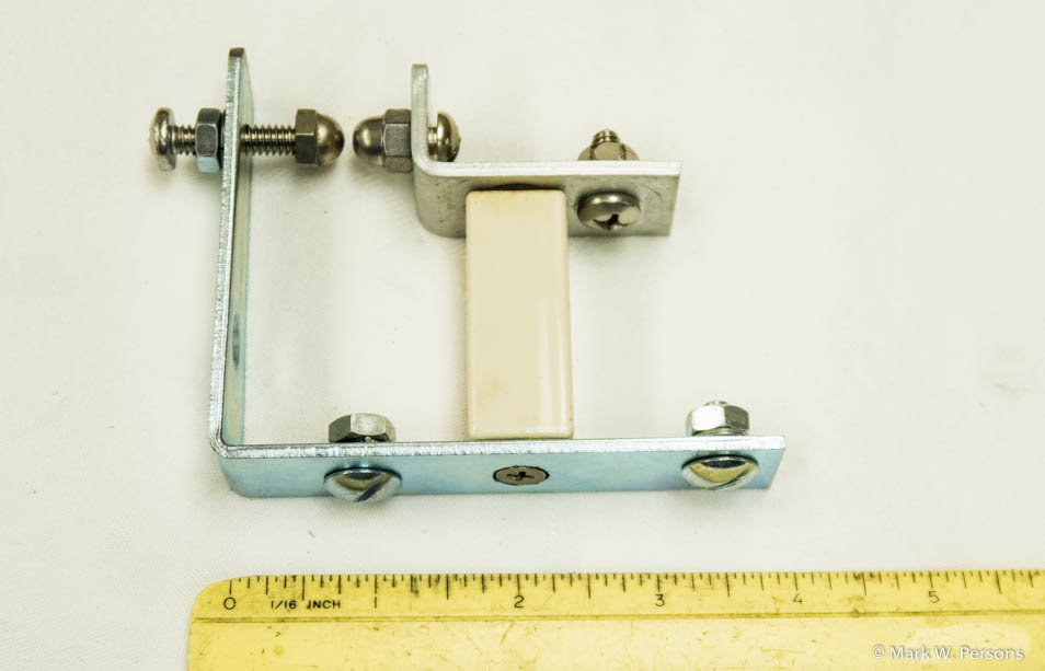
| Here is an example of an inexpensive
arc-gap for use in AM antenna systems.
Gaps like this are proven technology to
help protect AM broadcast equipment against lightning strikes.
My preference is to put one
at the 50 ohm input and the antenna output of all antenna coupling
networks. They should also be installed in AM phasors where lines enter from
each tower. Another good place for one is at the input
side of the phasor where the transmitter feed line is.
The larger L piece is a standard 4-inch
plated corner
brace or angle bracket available at a local hardware store. Acorn nuts are used on each end of
the gap, which is good practice for this kind of device. I used
a 1/4-20 tap to put threads in the bracket. A 1/4-20 machine screw
with lock washer and nut allow for adjusting the gap dimension without
laying hands on RF, which is normally on the other side of the gap.
The smaller L bracket is made of aluminum and is also threaded to
accommodate plated brass hardware. I use non-ferrous metals in RF
circuits because they will not vibrate at the
radio frequency, heat up, and sometimes melt. You gotta think
about these things! If in doubt, use an ordinary bar magnet as a
test tool.
If the hardware is attracted to the magnet, then don't use it for RF.
Yes, the larger angle bracket is steel, but it is not on the RF side, it
is on ground and not conducting RF. The porcelain insulator in the middle is
bolted to the two L brackets. The bottom bolt has a flat head and
is recessed to be flush with the surface of the bracket. Two steel
bolts with lock washers and nuts will hold this arc gap down, usually to
a metal surface. |
 |
||||||||
|
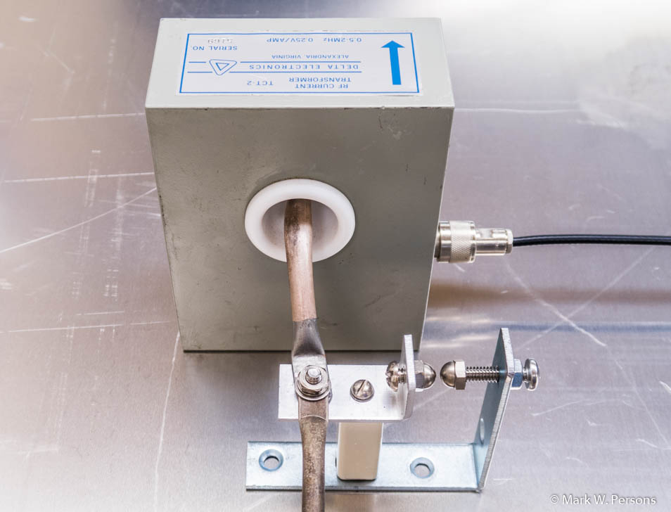
It is especially critical to install an arc gap wherever the system has a Delta brand antenna ammeter or toroidal sample coil, as shown above. The best location is on the antenna side of the sample coil where lightning is most likely to come in. Run the RF conductor as close to the center of the coil as possible. Remember, lightning will take the shortest path. That gap should be larger than the arc gap. If the coil has a black mark across its white Teflon bushing, chances are it has been hit by lightning. The usual symptom is the sample output voltage will double, causing major metering problems. Arc gaps of this type should be used inside and not out in the weather. In addition, you want to mount them in such a way that the acorn nuts are horizontal from each other. That will allow an arc to quickly clear, much like a Jacob's Ladder, not to be confused with a movie of the same name. Mounting one above the other can lead to a continuous arc that does not easily quench. One important attribute of this design is the arc distance is held constant over time because of rigid mountings. You don't want it to be flimsy. Setting the arc gap can be interesting too. How much is enough or too much? The Nautel transmitter people published a paper with dimensions. It showed:
All of that assumes 50 ohms impedance with no reactance at sea level. For me it is easier to set the gap wide, then bring the distance closer while the station is fully modulated. AM modulation, as you know, adds 50% or more to the RF power on peaks. When an arc occurs, I back off the gap to twice that distance, then tighten it down. Routine maintenance should include checking all arc gaps for cleanliness. You might be surprised to see that gaps have been badly pitted from arcing. Be glad that they have helped save the equipment while sacrificing themselves in the process. It is cheap insurance. |
|
The stories go on and on.
Stop in again sometime. I'll leave the soldering iron on for you.
|
|
Questions? Email Mark Persons: teki@mwpersons.com |
.