 |
|
|
|
|
||||||||||
|
|
|
||||||||||
|
Technical
Tips from Mark W. Persons |
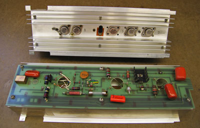 Those who work on Harris MW-1 or MW-1A AM Transmitters will recognize
these 14-inch long power amplifier modules. It takes thirteen of
these to equip a transmitter to run at 1000 watts. One is an RF
driver and the other twelve are power amplifiers. Each module has
two RF transistors and five audio transistors. Depending on
conditions, it is expected that there will be one module failure on
average per year in these transmitters. Those who work on Harris MW-1 or MW-1A AM Transmitters will recognize
these 14-inch long power amplifier modules. It takes thirteen of
these to equip a transmitter to run at 1000 watts. One is an RF
driver and the other twelve are power amplifiers. Each module has
two RF transistors and five audio transistors. Depending on
conditions, it is expected that there will be one module failure on
average per year in these transmitters.Repair these modules by first checking each of the transistors for gain and leakage when each device one has been removed from the circuit. Just checking for a short in the transistors is not enough as some of them go open, and will not show a short. Then, check for any shorts across the insulators under each transistor. Careful attention is paid to putting just the right amount of silicone-based heat transfer compound on both sides of the insulators. Also check the diodes and fuse. Any new replacement components should be checked before installation. When reinstalling one of these modules in a transmitter, it is recommended the module be fully pushed down into the edge-connector socket. Then, both top mounting screws need to be snug, but not over tightened. Too tight and the screw will break or strip the threads. These screws are the RF connection to the transmitter chassis. Failure to tighten the two screws will result in burned contacts on the bottom edge-connector and socket. Repairs are definitely more expensive then. |
| Popular upgrades include replacing TIP-47 Transistors with TIP-50 Transistors, which have a higher voltage rating. The original 2N6340 RF transistors can be replaced by SJ3125 or 2N5038. That change dictates a circuit modification, recommended by Harris in their bulletin AM-141-CKH from June 1980. 2N6254 audio transistors can be changed to MJ15024. Do so at your own risk. Disclaimer. |
 |
 |
|
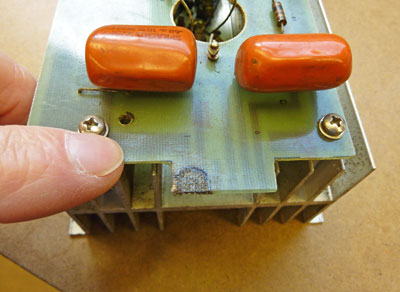
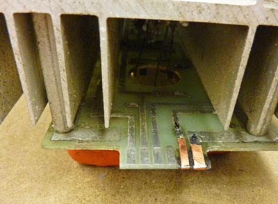
The above photos
are of a module which has burned contacts on its edge connector.
This happened because the two mounting screws were not tightened down in
the transmitter where the module resides. Those screws, near the
top of the module, are the RF ground. If the module cannot find a
proper ground there, it will attempt to use the power connector at the
bottom and will burn the contacts on the board and in the mating socket
in the transmitter. |
 |
 |
|
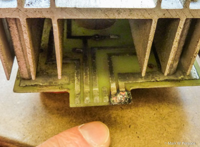
When
running into module damage like this, best to clean the fiberglass board and
then use a two-part epoxy to build up the circuit card to its original
dimensions. Then add adhesive-backed copper foil. That
copper is then soldered to some of the original traces on the card to
give a good low-resistance path for power.
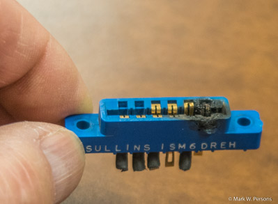
On the right is a burned connector from the transmitter chassis. Again, the burn-out is the result of not gently tightening down the module before turning on the power. It is unfortunate that replacement connectors are difficult to find. |
|
The stories go on and on.
Stop in again sometime. I'll leave the soldering iron on for you.
|
|
Questions? Email Mark Persons: teki@mwpersons.com |