 |
|
|
|
|
||||||||||
|
|
|
||||||||||
|
Technical
Tips from Mark W. Persons |
|
|
On the left is a wall-mounted
1000 watt AM dummy load consisting of seven power resistors. It was
located at a transmitter site along with an RF contactor and ammeter to
determine current into the dummy. The contactor has two transmitters as
its inputs. There is the antenna (tower) on one output and the dummy on
the other output. The plan was to connect the dummy load to the transmitter
that is not going to the antenna at that moment. All is well except for a few issues. The first is RF exposure to people nearby. RF levels will exceed 100% of the OSHA limit at as much as six inches away from any of the exposed conductors. Touching one of the conductors could result in an RF burn. The second problem is with exposed 120 VAC on the terminal strip along the bottom of the contactor. Definitely a hazard that an electrical inspector would not like to see. |
 |
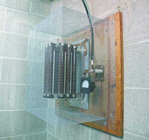
After a little rework at the
transmitter site, the RF contactor was removed and replaced with an
RF switch in a metal box elsewhere in the facility.
What remained was the dummy load and the ammeter. They were enclosed in a
cage made of hardware cloth. This cloth has 1/4" square holes and is very
rigid once it is carefully stitched together along the corner seams. Just
putting the cage on does not make the load safe. The cage was connected to
ground. You can't see it in the photo, but that is how it was built.
If the cage was not grounded, the cage would have become an antenna that would
have been dangerous to touch.
Thanks to Wendell Sowers at KXRA Radio in Alexandria, Minnesota, for his expertise in reworking this dummy load. All's well that ends well. Story from August 8, 2011. |
|
The stories go on and on.
Stop in again sometime. I'll leave the soldering iron on for you.
|
|
Questions? Email Mark Persons: teki@mwpersons.com |