It seems that every time we turn around
there�s another power problem to solve. We may be radio broadcast
engineers but we need power to keep a station on the air.
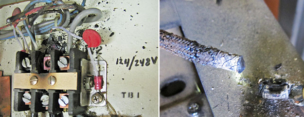
Fig. 1 is from the inside of a broadcast transmitter where 240 VAC
power comes in. A loose connection
on the power connector block caused wires to burn off. Wires have
been pulled back from the top center terminal of the block to show
the debris left from the incident. Insulation burned off the
overheated wires for about two inches from the block. The connector
will need to be replaced after a temporary repair is made.

|
|
Left: Fig. 1, Right:
Fig. 2 |
|
The photo shows a Harris HT-5 FM but this kind of problem can and
does happen to all transmitters where high-current conductors are
terminated. Best to check tightness of these kinds of connections
whenever practical.
Fig. 2 shows a similar incident in a Continental 816R 20 kW FM
transmitter. A heavy 208 VAC wire on the primary of the high-voltage
power transformer is burned off.
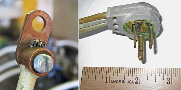
I have seen this twice over the years. The original crimped terminal
gets warm and then hot as resistance increases. The wire often needs
to be cut back five inches or more to find clean copper. A field
replacement can be a screw terminal as shown in Fig. 3.
Fig. 4 shows a 120 VAC plug that was providing power to three
equipment racks in the engineering area of a radio station. The
cable-to-plug wiring developed higher-than-normal resistance
resulting in overheating. The insulation on one conductor turned
brown from the heating. As you can see, the plastic on the plug
suffered as well.

|
|
Left: Fig. 3, Right:
Fig. 4 |
|
The problem was caught on a routine inspection when it was noticed
that the plug was running hot. This plug would have gone into total
failure after not too much longer. The wall outlet didn�t look very
good either.
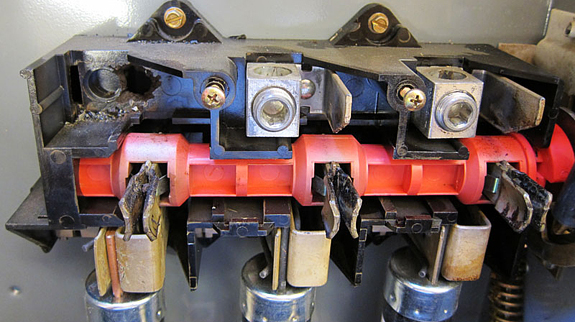
Fig. 5 is the top/input end of a three-phase/200 ampere fused
disconnect switch used at a transmitter site to provide 240 VAC
power to a 25 kW FM transmitter. The leftmost lug is missing because
of overheating. The left fuse was replaced temporarily because it
failed from heat fatigue. The center and right fuses are discolored
and also were discarded after the switch was replaced because it is
good engineering practice.
The lesson here is that reliability is more important than saving a
buck.

|
|
Fig. 5
|
|
The panel was a Square D model D324N. It had been in service for
just nine years. Two years earlier, an identical panel was replaced
on another transmitter at the same site.
That is a bad track record considering less than 120 amperes of
current were being drawn per leg. Electrical practices dictate that
loads should be no more than 80 percent of the capacity of the
panel. In this case, 120 amperes is just 60 percent of 200 amperes.
That should be plenty of safety margin. I suspect that Square D had
a problem with this panel design. The replacement panel was made by
Siemens.
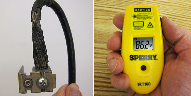
Fig. 6 is the left input lug of that same panel after it was gently
lifted out. The 3-0 wire connected to it had overheated and its
insulation was largely fried off. Not only did the fused disconnect
need to be replaced, but the wire leading to it needed to be
replaced.
There are inexpensive infrared thermometers that can spot
overheating problems before they become big. Fig. 7 shows a Sperry
IRT100 temperature sensor, with laser pointer. It was less than $50
from the local Home Depot store. The moral of the story is that
preventive maintenance can save you problems later.

|
|
Left: Fig. 6, Right:
Fig. 7 |
|
|


