Retired after 40 years in business  

 
Home
About
Used Equipment
Articles Written
Speeches Given
Tech Tips
Web Links
Radio History


   Articles for the Radio Broadcast Industry

Terms of Use & Disclaimer


Quick, We Need a Temporary AM Antenna

by Mark Persons
Radio World Article
January 27, 2021

 
Here's what happened after a crew declined to climb WJMC's old stick
 
Fig. 1: WJMC Studio with temporary antenna

Mike Murrey hired on as engineer at WJMC(AM/FM) and WAQE(AM/FM) in Rice Lake, Wis., back in 1998. He took one look at the 459-foot tower serving WJMC on 1240 kHz and knew it would need to be replaced someday.  Well, that someday came in late 2019 when a crew refused to climb the 63-year-old structure. That started a chain of events to replace the tower.

Heavy and consistent rains made site preparation exceedingly difficult. Temporary roads were built with rock and gravel so concrete could be poured at the new tower base and guy anchor points. The original concrete could not be used because towers are now “engineered” so they can be insured by insurance companies.

It was beginning to look like the project would extend into 2020 when the tower crew announced they were starting “right NOW” to take the old tower down. Rather than disassemble the old tower a section at a time, they elected to cut a guy anchor and let ’er fall. (Watch the video.) People were evacuated from the studio/transmitter building and a nearby business for the tower to come down. Besides, who would want to be inside working while a spectacle was going on outside?

Hurry

It had been assumed that there would be more than enough time to put up a temporary AM transmit antenna, but now there was a scramble to make it happen.  Mike’s original plan was to have two utility poles put up to support a long-wire antenna. My experience with horizontal wire antennas is that they make good “cloud burners,” as we say in the amateur radio hobby — RF radiation tends to go up rather than out to the horizon. I found that to be the case when helping another station. The coverage with a quarter-wavelength wire, from the tower base to a tree, went only a few miles. Ouch!

Details

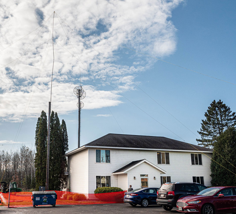
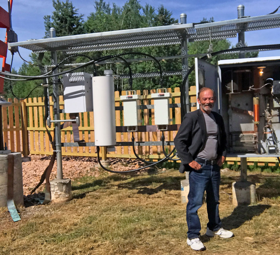
A better choice was to erect the tallest possible temporary vertical antenna.  The local power company installed a used 40-foot utility pole with 35 feet sticking out of the ground as shown in the image at the beginning of this article.

Topping that was 40 feet of pipe bolted to the pole. A wooden dowel was inserted inside the bottom pipe section to keep it from crushing when mounting bolts were tightened down. There was a fair amount of pole to pipe overlap. The top turned out to be only 68.5 feet above the ground.

The pole consisted of four 10-foot sections of iron plumbing pipe, reducing from the bottom 1-1/4 inch to 1/2 inch at the top. To help with antenna efficiency, Mike constructed a “top hat” of three 10-foot wires, at the top, attached to nylon guy lines. These wires were bare #10 soft-drawn copper. It was the same wire that is normally used in AM ground systems. They helped make the electrical height of the antenna a bit taller. A #6 stranded copper wire ran down the wooden pole from the metal pipe at the top. The wire was connected to a used/temporary antenna coupling network at the bottom. Four 200-foot copper radials were run out from the base on top of the ground. Some half-length radials were also run bercause there was extra wire available on the supply reel. Might as well use it.
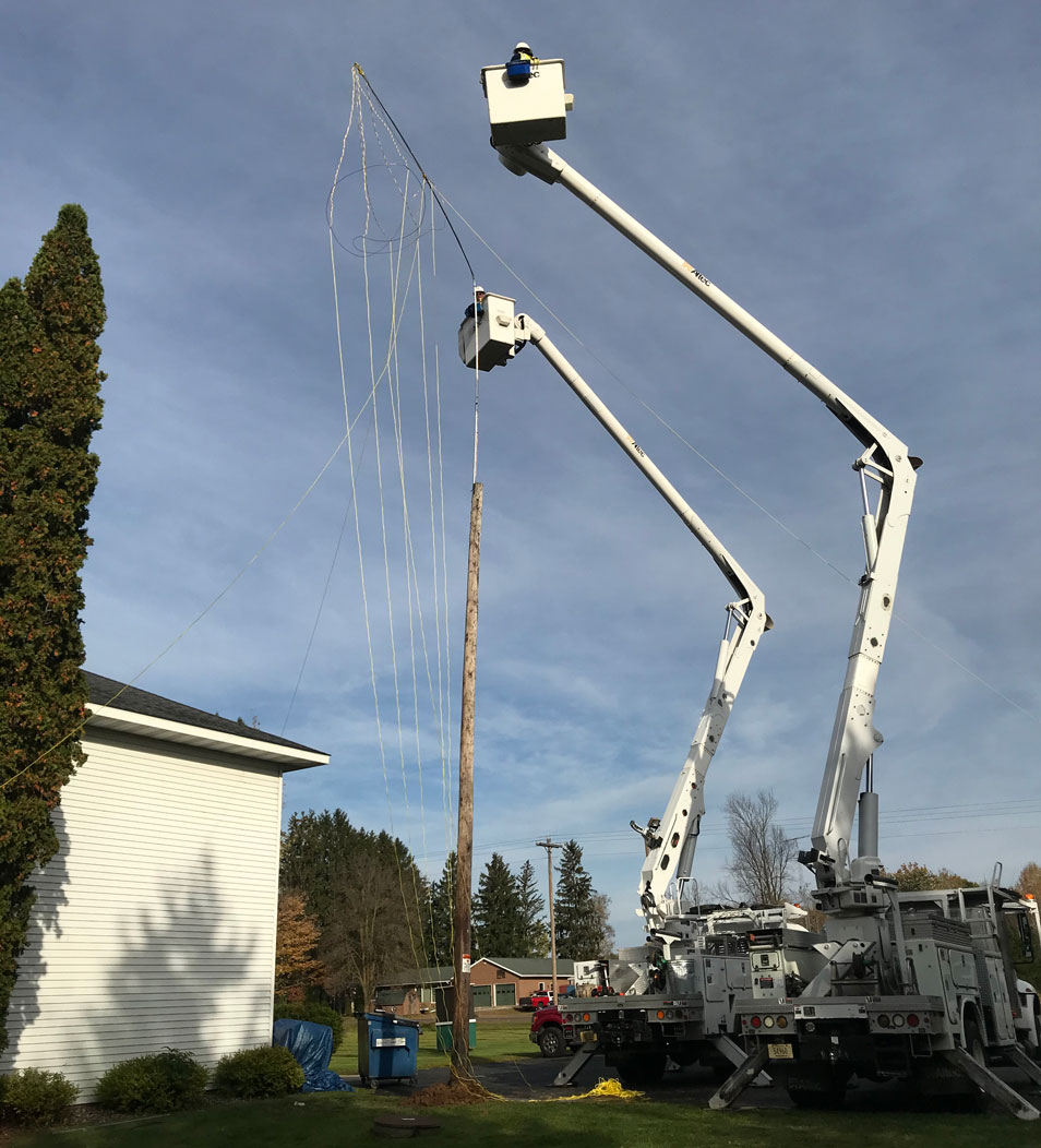
Things didn’t go exactly as hoped (Fig. 2).

Fig. 2: Raising the temporary antenna

Mike attached the pipe to the top hat while the utility pole was being put into the ground. Then the pipe bent over at almost 90 degrees while being raised into position. That required two boom trucks to help straighten the pole so it could be guyed. You will see it was still a bit bent in the photo.

After Dark

Contract engineer Del Dayton out of Eau Claire, Wis., was called in to measure the antenna impedance at night (Fig. 3).

Fig. 3: Del Dayton tuning the temporary antenna coupling network

He came up with 38 –J180, then calculated a design. Components were then installed and adjusted in a temporary antenna coupling network. It was convenient that the original 50-ohm transmission line could be pulled over and connected to the coupling network.

The downside is that the temporary antenna could not be constructed 100 feet away from the studio and original tower as originally planned. Instead it was located just off the parking lot some 10 feet or so from the studio. This is because trucks could not drive over the water-saturated ground.

The location presented its own challenges. Even though employees were kept RF-safe from the tower, RF got into unshielded cables leading to the fax and credit card processing machines. Mike relocated those to another part of the building.

Mike is a U.S. Air Force veteran and was laughed at by his U.S. Navy veteran brother. It seems Air Force guys don’t know how to tie knots in rope on guy lines. It takes a sailor to do it right!

He asked for and received special temporary authority from the FCC to cover the situation. He chose to run 250 watts, instead of the licensed 1000 watts, to keep RF at bay.

A Delay

Construction of the new 459-foot tower began, but soon the tower crew pulled off the job for three days to work at a TV station that was off the air. The foreman felt justified in doing that because WJMC was indeed “on the air.” The station manager and employees were happy because they still had listeners instead of being off for weeks. 

How well did it work?

The station had usable coverage. This intrepid reporter measured field intensity at 14 random points in the listening area using a GPS to document each location (Fig. 4).

Fig. 4: The author taking field intensity measurements

That allowed me to figure distance to measurement locations and plot them on a curve. This was a “Mark’s Two-Hour AM Micro-Proof,” as described in an article I wrote for Radio World in 2003 (read it at www.mwpersons.com/articles/6-4-03-RW-article.html).

The data revealed that the field intensity was 33 mV/m at a kilometer with only 250 watts of transmitter power. It was certainly better than nothing! There was about 10 mV/m in downtown Rice Lake and about 12 mV/m in residential areas. The population of this small Wisconsin town is 8,338 people. The half mV/m contour went out about 10 miles in their low ground conductivity of only 4.

The meter I used was a Potomac Instruments FIM-41. The FIM-21 and the PI 4100 are similar instruments that are commonly used for measuring monitor points on AM directional antenna systems. They are good tools for determining antenna efficiency, as you see in this article.

Before and After

I did the previous antenna resistance measurements back in 1993. It was 108 ohms with –247 ohms reactance for an antenna current of 3.04 amperes with 1000 watts input. Del Dayton measured the new tower as 43 ohms, –125 ohms reactance, for 4.83 amperes at 1000 watts. The details are in Fig. 5 below, which you can click to see enlarged. Yes, the two towers were the same height. 

Fig. 5: Schematic diagram of the WJMC antenna system. 

A lot of factors can change the characteristic impedance including tower width, antennas on the tower, isocouplers, lighting chokes, capacitance to the tower from the guy lines and lead-in to the antenna coupling network.

I now believe the old tower had a bad electrical connection between tower sections near the top. Yes, this can happen as towers rust. Sections can become electrically disconnected, even with tons of downward pressure. Hard to believe, but it is true. That is why at least one leg needs to be welded at joints. Learn more on an article I wrote in Radio World in 2012, “Better Living Through Tower Welding”. Mike had the crew weld two tower legs because it was convenient for the welder when doing the work.

In Fig. 6, Mike Murrey shows off the completed project with new isocouplers and a rebuilt AM antenna coupling unit. The new tower has FM translators for their two AM stations and a backup antenna for their three full-power FMs.

Fig. 6: Mike Murrey and the completed project

Mark Persons, WØMH, is a Certified Professional Broadcast Engineer and recent recipient of the SBE John H. Battison Award for Lifetime Achievement.  His website is www.mwpersons.com.


Also find the article at: https://www.radioworld.com/tech-and-gear/tech-tips/quick-we-need-a-temporary-am-antenna


Emails:
01-31-2021:  Great article including pictures that help tell the story.  Thanks.  Lyle Amundson, Merrifield, Minnesota.

01-31-2021:   Hello Mark:  Yeah...neat article about that 459 ft tower replacement.   Phil Schoenthal, Poco, Washington.


01-29-2021: 
Mark,  Last night I read your article in the latest Radio World.  I am a retired TV engineer in Louisville.  I still try to stay up to date with technology.  I enjoyed your story. Gil Lochner.

01-31-2021:  Mark. It is a very well written article (as usual!).  I particularly liked that you mentioned and addressed the impedance difference and possible reasons.  Much agreed on welding.  I've heard many DA stability "horror stories" due to that.  Hopefully it will help some AM newbies.  Thanks for a great article (and all those you write).  The temporary vertical antenna was the way to go.  Del Dayton, Eau Claire, Wisconsin.
 

     Questions?  Email Mark Persons:  teki@mwpersons.com       

    Return to Home Page    Return to the Articles Page

.