
|
Retired after 40 years in business |
 |
|
|
|
|
|
|||||||||
|
|
 |
||||||||
 |
Making Sense of Component Level Troubleshooting by Mark Persons |
Radio
World Article November 24, 2018 |
|
Dig inside those devices and figure out what’s going on to save time and money. It’s important to learn and use component-level troubleshooting skills to diagnose and repair electronic problems, even in today’s world. |
 |
|
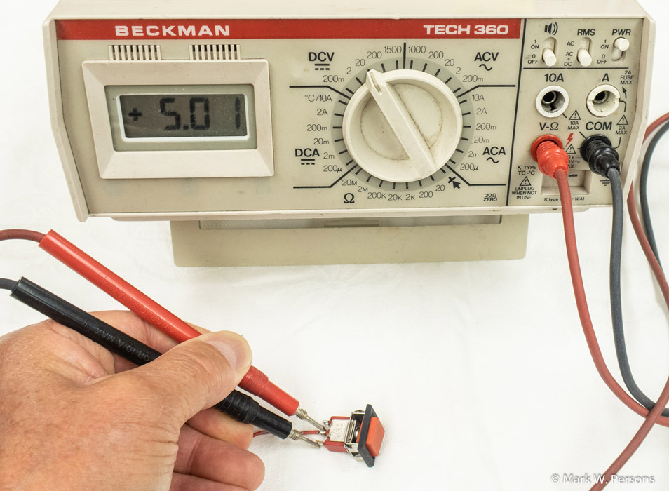
Fig. 1: Use a voltmeter to figure it out. |
|
The process involves digging into an electronic device, usually analog, to find and replace a failed component. Sometimes this means tuning and/or calibrating the equipment to manufacturer’s specifications before returning it to service. This has been a part of broadcast engineering since the beginning, when every piece of gear was hand-crafted. (I described that in a story in November titled “Yes, You Can Build Your Own.”) New transmitter designs make troubleshooting easier, with displays and lights indicating which module has failed. But that only goes so far. What if the front-panel push-buttons fail to work? Do you assume the button is bad and should be replaced? You might find a new button won’t get the transmitter up and running again. Imagine that — ordering and waiting for a replacement pushbutton switch to be delivered while a transmitter is off the air. That assumes a lot. Don’t laugh — I’ve heard of it happening! Test with a multimeter to see if normally open push-button switch contacts have voltage across them, which goes to zero when the button is depressed. You might even use a clip-lead jumper to see if the transmitter might be restarted without the switch … assuming you can do it safely. First, read the schematic diagram to confirm the switch is normally open and determine what the expected voltage is across it. I know this sounds elementary to many broadcast engineers, but it illustrates how troubleshooting can be simple yet still solve a big problem. Guessing is a bad troubleshooting technique. It’s best to visualize what the circuit should be doing and determine likely reasons it is not performing as expected. Measure voltages to see what isn’t working as designed. My self-education started by reading books that showed simple circuits with switches and lights, much as you’d find in a home electrical system. Learning progressed from there, one step at a time. One standard troubleshooting procedure is called “divide and conquer.” You use that now when a station goes off the air due to an STL failure. The equipment is in series, so it is relatively easy to diagnose where the audio stops. Analog audio consoles are similar in that the audio goes in and may stop along the way before it can come out. It’s nothing difficult, just think it through. Old-time engineers often built equipment to solve problems around their stations. An example is a microphone cough switch. It might be as simple as a box that intercepts a microphone cable with a normally open pushbutton switch to short the two wires of microphone audio when depressed. It’s not magic, just common sense. FAILED COMPONENTS Electronic components can look perfectly good on the outside and be bad on the inside. |
 |
|
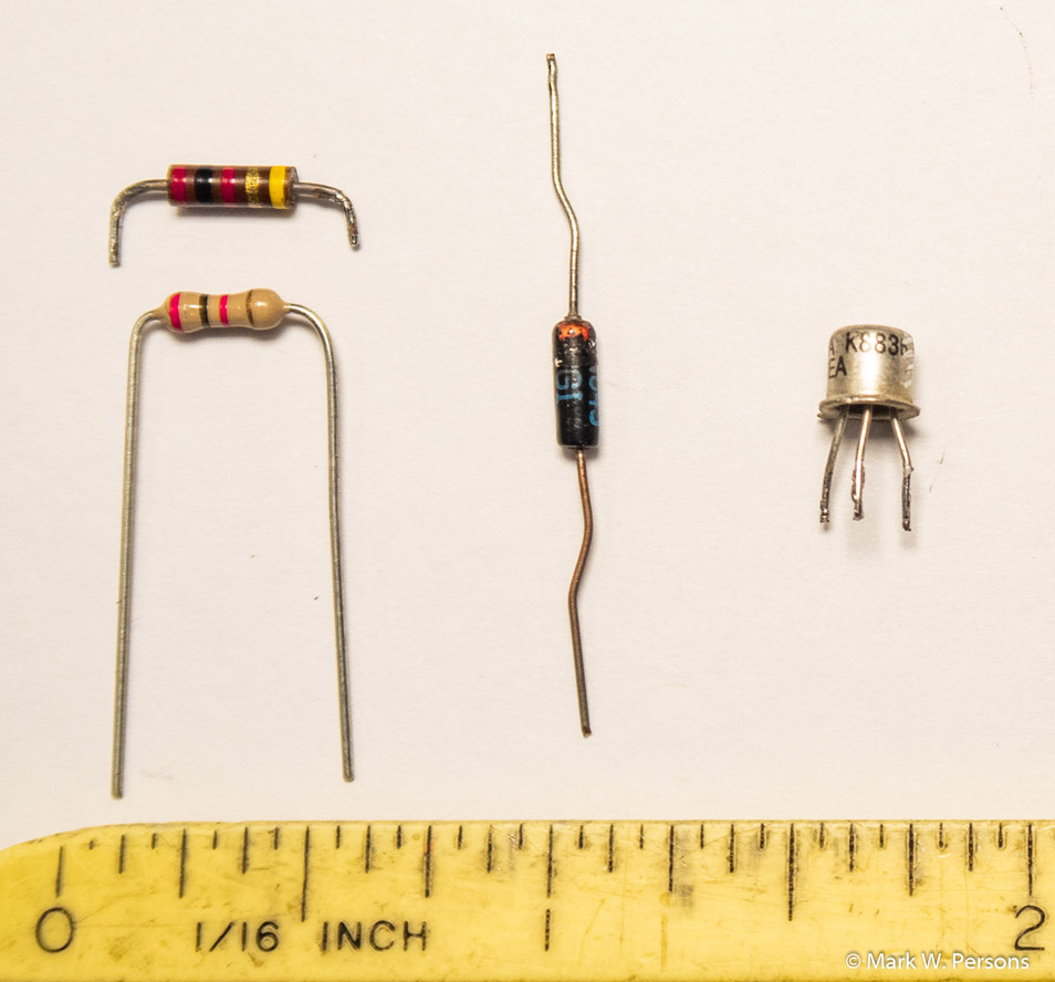
Fig. 2: Failed parts that look perfectly good on the outside. |
|
Fig. 2 is a case in point. The part in the upper left of the photo is a carbon composition 2000 ohm resistor. It shows no sign of heating or cracking. I found this one in an FM exciter causing trouble. It measured in at about 20,000 ohms — some 10 times its rated value. The resistor below it is of a carbon film design, which made an excellent replacement. Carbon film resistors are much more reliable but have some inductance, which could be a problem in a very high frequency RF circuit. The diode in the center of the photo came from a 1960s vintage Collins 5 kW AM transmitter. It’s job was to steer DC logic to turn the transmitter on. The diode opened and disabled the start function. We normally think of diodes as failing shorted. Not in this case, it went open! Diodes are easy to check using the diode function on most multimeters. They should show about 0.6 volts drop in one direction and open in the other. The transistor in the right side is a 2N2222A. I found this one going open in a Continental 802 series FM exciters. It is used in the RF mute circuit. Without it working properly, I couldn’t get the exciter’s RF to turn off. It took component level troubleshooting to find all three of these. Learning and using that skill is still important in today’s plug’n’play throw-away world. What is the sense of trashing a $5,000 FM exciter when a $2 part might make it run again?
ELECTROLYTIC
CAPACITORS Electrolytic capacitors are something like batteries. They are charged with energy and then they release it, as planned in a circuit design. A good example is capacitors in a power supply. If they are preceded by a full-wave rectifier system, the capacitors will charge and then discharge at a 120 Hz rate to keep the DC level constant. They do this while circuits in the equipment are drawing current from them. That is a hard job and they get tired after 10 years or so of continuous use. They lose their capacity to do the work and are often referred to as “dried out.” In an analog piece of gear, the first symptom is usually hum or no bass in the audio. As I said, save time and trouble by replacing them all. You’ll be glad you did. Have spare capacitors on hand. In my business I stocked almost all values so they were available immediately when a piece of equipment came in for service. The downside is that the stock will go bad with time. It must be rotated to make sure all capacitors are fresh. The good side is that electrolytic capacitors are inexpensive. You might purchase a 470 mfd/50 VDC capacitor for just $0.68 from Digi-Key or Mouser. I usually ordered at least 10 at a time. Let me warn you that not all electrolytic capacitors are the same. They are rated for current handling, temperature and reliability. If you don’t feel comfortable making buying decisions, let a more experienced technician do the work. Or order directly from the manufacturer of the equipment you are repairing. They will know exactly what is needed, and will charge accordingly. Usually you won’t go wrong when replacing capacitors, but some circuits require capacitors that are heavy duty or have low ESR (Equivalent Series Resistance) found in tantalum or more exotic capacitors. You don’t want to mix those. You are safe when using a 50 volt capacitor in a lower voltage circuit where only say 25 volts will be across it. Don’t do it the other way around. Capacitor voltage ratings should not be exceeded. |
 |
|
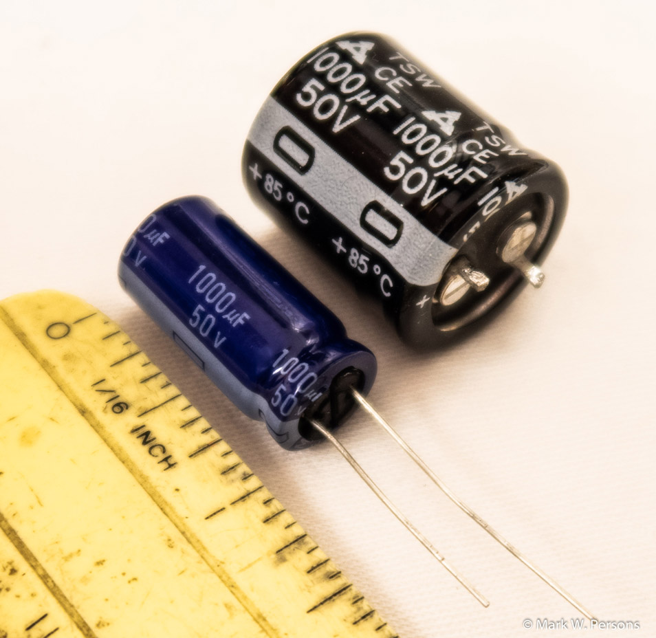
Fig. 3: Two capacitors of the same value for different jobs. |
|
Fig. 3 shows 1-inch-long capacitors of the same electrical value. What is the difference — and isn’t cheaper better? Well, the larger one, 0.866 inch diameter, is used in a power supply where it needs to work hard to take pulsating DC and turn it into steady DC. The smaller one, 0.492 inch diameter, might just stabilize a circuit with little or no voltage ripple. Using the smaller one where the larger one belongs will likely work for only a while. You’ll probably be back working on the equipment less than a year down the road. Not a good choice! Think the job through to save yourself time and trouble. It makes perfect sense.. |
|
This is a reprint of the article which appeared in the online
version of Radio World at:
https://www.radioworld.com/tech-and-gear/making-sense-of-component-level-troubleshooting Mark Persons, WŘMH, is an SBE Certified Professional Broadcast Engineer. He recently retired after more than 40 years in business. His website is www.mwpersons.com |
| Email: December 1, 2018: Good Article! Hi Mark, I enjoyed your article on troubleshooting in the recent Radio World. Merry Christmas to you and Paula. Again , congrats on the well-deserved SBE award. Maynard Meyer, KLQP Radio, Madison, Minnesota. |
|
Questions? Email Mark Persons: teki@mwpersons.com |
|
.