|
A violent, straight-line wind came through
Brainerd, Minn., in the summer of 2015. Suddenly, operating
parameters changed on the KLIZ(AM) 5 kW ND day and 5 kW
three-tower directional night antenna systems. Not serious,
but enough to notice.
Apparent transmitter efficiency decreased
because of a shift of a few ohms in day tower impedance.
Night tower phases changed 2 degrees and ratios about 3
percent. Tweaking phasor controls to get licensed phase and
ratio resulted in normal night monitor point readings.
Still, something was amiss.
A tower crew was brought in to inspect for damage.
 |
|
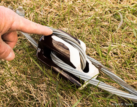
Fig. 1: A partially shattered guy-line
insulator. |
 |
|
Fig. 2: Insulator half gone from a guy line. |
From a high vantage point they found that about a dozen of
the original guy line insulators were damaged or outright
broken on the 380-foot tower at the center of the array. The
violent wind had whipped the lines mercilessly.
 |
|
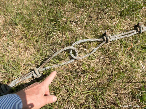
Fig. 3: Insulator completely missing from a guy
line. |
At least one insulator broke away entirely,
causing metal guy line sections to be electrically
connected, rather than insulated from each other. These are
sometimes referred to as ?Johnny Ball? or ?egg? insulators.
It is a good thing that insulators are designed and built so
that failure will not result in guy line separation. The
photos you see were taken when the damaged insulators were
finally on the ground for close-up inspection near the end
of the project. It is important to note that a cracked
insulator can arc over, especially when the crack fills with
debris and water.
The repair was a big job. It was determined ultimately that
all guy lines and insulators on the tower had to be
replaced. The insulators are spaced at one-tenth or less
wavelength intervals. At 1380 kHz, that is 71 feet, so there
are quite a few.
Not all tower contractors know the requirement to put
insulators in guy lines at the correct intervals. You, as
the engineer, must watch over the project to make sure it is
done right.
Time went by because the insurance company
had to agree to the repair, then supplies were ordered and a
tower contractor was hired.
I measured AM monitor points just before the tower crew
started the repair. It was a reference point in case
something went wrong. I could pin any new problem on the
work, not something that might have happened a month or more
prior.
Since KLIZ is a multi-tower array, I was able to divert AM
power to the north tower, which is 180 feet away. I did that
at 1,000 watts instead of the 5,000 for which the station is
licensed. That was to keep the tower crew safe. I also
grounded the unipole feed on the troubled tower to keep AM
RF voltages to a minimum while workers were on it. Grounding
was by a heavy cable with large alligator clips (as
described in my Radio World article in the July 6, 2016,
issue).
KLIZ is non-directional day, as mentioned, so it worked out
using a single shorter tower in the array during the day,
even if it was not the one normally used. By sunset, the
plan was for the station to go directional, as required by
FCC rules.
 |
|
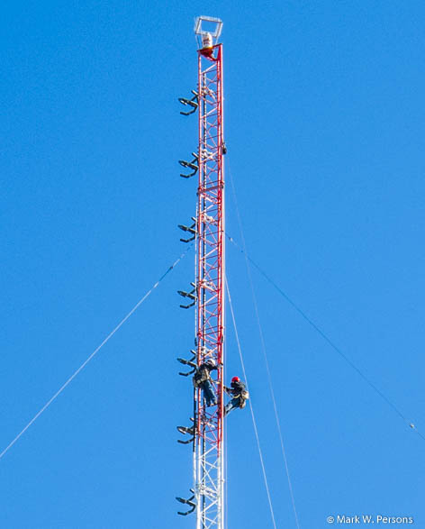
Fig. 4: Workers on the tower near an FM antenna. |
The tower requiring work has two FM transmit antennas. The
FM transmitters had to be reduced in power or completely
shut down for much of the project. Station management and
programming weren?t happy about it, but what could they do?
Safety comes first.
The procedure involved installing and
tensioning a temporary guy line to a slightly higher
location on the tower than the original guy. Then the
original line was taken down and a new line hoisted in its
place. That new line had to be tensioned while tension was
being released from the temporary line. It was a slow job
that took three men a week to complete.
The first day ended in the installation of a temporary guy
line that did not have insulators. Directional operation
that night was impossible because the tower became,
electrically, an odd length that could not be compensated
for in the phasor system. So that was a lesson learned the
hard way. From then on, any temporary guy line was insulated
from the tower so it would not significantly distort the AM
directional night pattern during the project.
 |
|
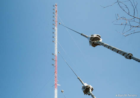
Fig. 5: Guy lines properly tensioned. |
|
Guy lines droop slightly, but that is normal when they are
tensioned properly. Good engineering practice dictated that
I confirm all AM operating parameters. Fortunately, they had
returned to normal before I released the tower crew to go
home. That included measuring AM monitor points while the
crew was still cleaning up on the ground. One essential
element in this lesson is that thinking ahead will help
avoid problems later.
All was well after the repair work was done. The towers
stood tall at sunset for everyone to admire. They have been
there for 48 years and should be around for a while longer,
providing broadcasting to the area.
This article is not just about what I did, but about what
you should do in a case like this. Also, if you have an AM
tower that has changed impedance, it might be good to pull
out binoculars to see if one or more of the guy insulators
is broken, especially where a guy line meets the tower. It
makes perfect sense to check everything.
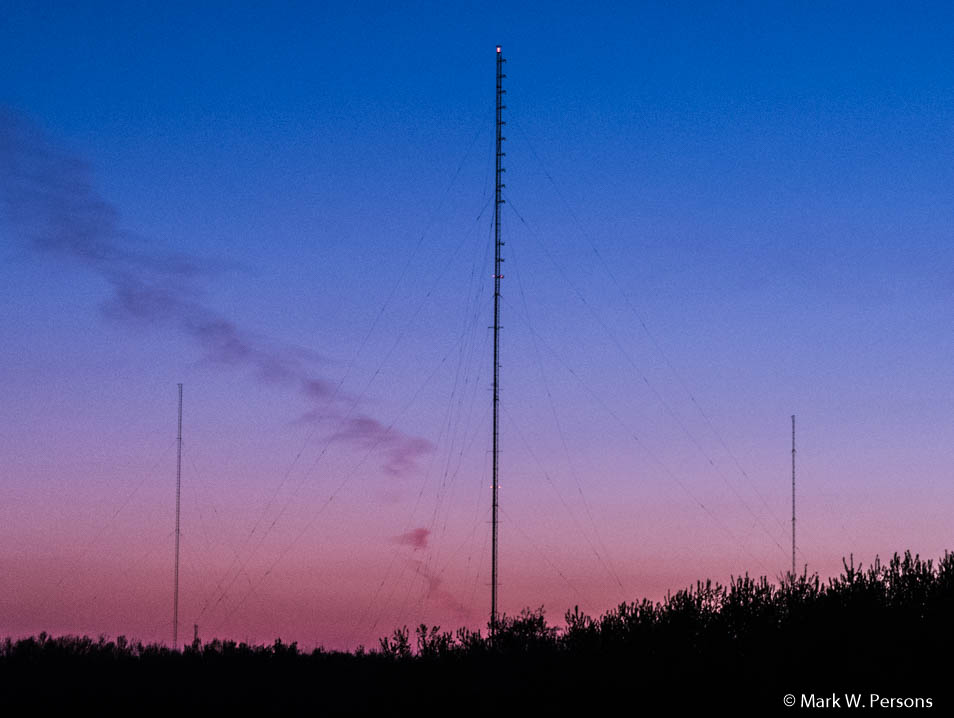 |
Fig. 6: Sunset at the end of the successful
project.
|
Mark Persons, W0MH, is a Certified Professional Broadcast
Engineer and has more than 40 years? experience. His website
is www.mwpersons.com.
The Internet version of Radio World can be seen at:
http://www.radioworld.com/tech-and-gear/0003/lessons-of-a-major-guy-line-project/339265 |


