 |
|
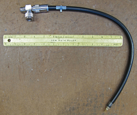
Here is a
shorted quarter-wave
stub with N T
adapter ready to
connect.
|
Ever wonder what causes a
solid-state RF amplifier to
fail? One answer is heat;
the other major contributor
is transient voltages. Most
of us know to keep equipment
cool, but few understand
that voltage spike-induced
transistor failures can be
prevented with pure science.
Tube arc-overs create
voltage spikes in
transmitters. Because of
that, I highly recommend a
shorted quarter-wave stub
after any solid-state
amplifier feeding a tube
input. They normally go at a
50-ohm point in the system
and provide a DC short to
voltage spikes, while
passing RF with little or no
loss.
Continental Electronics has
long suggested these for its
FM exciters. I build them
for clients and you can,
too. (Just contact me via my
website if you have
questions.)
RF theory and practice tell
us that a quarter-wavelength
of transmission line will
ignore the frequency of
interest if it is on a T
adapter in the RF path and
is shorted at the far end.
That's right, you short the
center conductor to the
outer conductor at the end
of the cable. The short will
be what DC or transient
voltage spikes will see. The
trap will short everything
but the frequency of
interest.
In the case of an 88 to 108
MHz FM system, a 50 ohm
RG-58, RG-8, RG-213 or
similar coaxial cable is
just fine for the use. The
important part is that the
cable needs to be sized in
length for the frequency you
want to pass.
As you know, each coaxial
cable type has a VF
(velocity factor). So a
quarter wavelength of line
would not be the same
physical length as a quarter
wavelength in free space.
Let�s say you are operating
at 98.1 MHz. A wavelength at
that frequency is 120.4
inches (about 10 feet). A
quarter of that is 30.1
inches.
 |
|
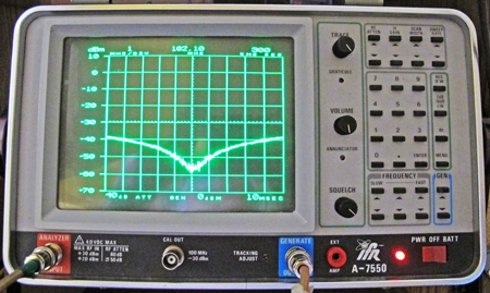
A spectrum
analyzer displays
return loss at and
near the frequency
of interest.
|
RF travels much slower
when going through a
transmission line. A typical
example is Belden 8259
RG-58A/U. Its velocity
factor is 66 percent. To
achieve an electrical
quarter wavelength at 98.1
MHz, that line needs to be
66 percent shorter, which
turns out to be 19.87
inches.
Making one of these will
require a connector on one
of the cables. I wrote an
article about that subject
in Radio World last year ("Installing
the Connectors the Right
Way" Oct. 10).
Hopefully that will help.
You can do fairly well by
calculating the line length
for a particular frequency,
but there is the length of
the T adapter to contend
with. I use a return loss
bridge to trim the cable
length experimentally so
that it is exactly on
frequency.
THE SETUP
Put a 50 ohm dummy load on a
return loss bridge connected
to a spectrum analyzer with
tracking generator. Then
sweep the frequency of
interest. Your test
arrangement should show 30
dB or more of return loss
when the dummy load is
attached.
Install a T adapter in
series with the dummy load
and the result should be the
same. Connect a piece of
coaxial cable to the open
port on the T, and your
return loss will become
terrible. Use wire cutters
to cut into (but not
through) the line, at a
length longer than you
calculated or think it will
take to make the trap.
Cut through just enough to
short the center and outer
conductors together. The
spectrum analyzer should
show a return loss dip at a
frequency lower than the
desired one. Then cut again
making the line shorter by
maybe 1/8 inch. The
frequency should go up.
 |
|
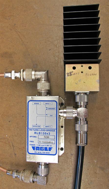
Here's the
test setup with a
return loss bridge
and dummy load
connected for
testing a shorted
quarter-wave stub.
|
When you get close to the
desired frequency, cut
through the cable entirely.
Then carefully bare the
center conductor near the
cable end and twist the
outer braid onto it.
Experimenting, keep trimming
just a bit at a time until
you are on frequency. Then
whip out your soldering iron
and solder the end of the
center conductor to the
outer conductor at that
point. Verify that the best
return loss happens at the
desired frequency. If the
frequency is too high, throw
the cable away and start
over. If it is too low, just
keep trimming the cable
shorter.
When you are done, you can
confidently install the
shorted quarter wave stub
trap with T adapter in a
transmitter or on the back
of an exciter. There should
be no change in VSWR.
When I build these traps, I
usually use RG-58 or RG-8
type cable. You will more or
less be pushed into one of
those two cable sizes
because the equipment will
have a BNC connector for up
to 250 watts or an N
connector for up to 1000
watts.
I even built one for a 10 kW
FM transmitter, using 1-5/8
inch rigid transmission
line. In that case, the
shorted quarter-wave stub
trap was used for
attenuating the first
harmonic (twice the carrier
frequency), which is
sometimes misnamed as the
second harmonic.
Another was built for 950
MHz, but it was less than
two inches long. The goal
was to protect an STL
receiver from lightning
surges.
In conclusion, I'd like to
say that the more we know
about basic theory, the more
we can use it to make
stations better.
Mark Persons, W0MH, is a
professional broadcast
engineer, certified by the
Society of Broadcast
Engineers. He has more than
30 years' experience and has
written numerous articles
for industry publications
over the years. His website
is
www.mwpersons.com.
|


