|
You work on
transmitters every day. Have
you ever removed a large
tube socket for repair or
replacement? It can be a
daunting task.
I hope you don't have to
do the job overnight when
you are tired. Mistakes are
made easily and can be
difficult to figure out
later. Plan on taking a few
hours, even a day. Don't be
afraid of the job but
understand that you need to
work in a logical way. Take
photographs as you go along;
it can help immensely during
reassembly.
 |
 |
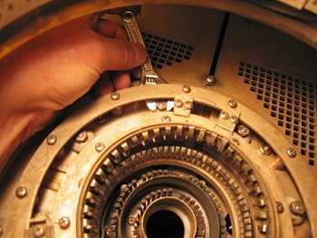
| Fig. 1:
Top of tube socket
with small wrench.
|
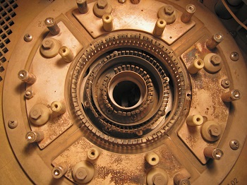
Fig. 2:
Bypass capacitors
around the tube.
|
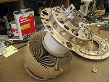
Fig. 1: Here is the
top side of a tube socket
for a 4CX15,000A tube in an
RCA BTF-20E 20 kW FM
Transmitter. Lots of pieces
in a small area. You can
never have too many tools
when doing this work. That
adjustable wrench is just 4
inches long. It is
exceptionally handy in tight
spots.
Fig. 2:
Here is the socket with the
screen contact ring removed.
Look closely and you will
see something is a little
odd on the left side of the
right-hand screen bypass
capacitor.
 |
 |
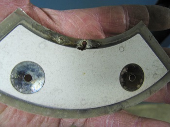
| Fig. 3:
Capacitor dielectric
that has been arced
through.
|
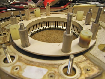
Fig. 4:
Socket removed from
PA cavity.
|
 |
 |
| Fig. 5:
Failed socket spacer
on the right.
|
Fig. 6:
Using a tube to get
socket parts exactly
in place.
|
Fig. 3:
Sure
enough, the insulator
material failed, causing a
short in the screen circuit.
You can see an arc-through
near the top. Careful visual
examination is an excellent
troubleshooting tool in most
cases. Fortunately there was
a spare part at the site.
Spares are a wonderful
thing!
In this transmitter
repair adventure, that
screen bypass was not the
only problem. The entire
tube socket had to be
removed for bench repair.
Fig. 4:
Note a scattering of
hardware in the bottom of
the PA compartment. A piece
of cardboard was placed over
the incoming air duct to
keep parts from falling into
the cooling fan. This is
also a good time to replace
any burned or broken
fingerstock.
The most likely failure
occurs on the innermost
filament contact ring. It
carries the same current as
the next ring out, but is
much smaller. The second
ring is the other side of
the filament. Current is 160
amperes in the case of a
4CX15,000A tube, which is
enough to start a car
engine. No wonder the
filament leads need to be
heavy duty.
Fig. 5:
On the bench, a nylon
spacer/insulator was
discovered to be the reason
why control grid voltage
went to nearly zero at
times, resulting in sudden
PA overloads. You can see
the insulator discolored
brown to black on the right
side of the socket. Since
those are no longer readily
available, I used a
porcelain insulator as a
replacement. This change in
capacitance is enough to
throw neutralization off.
Checking and adjusting
neutralization afterward is
a good idea when making
changes to the socket for a
tetrode (4CX) tube.
Triodes (3CX) don�t
require neutralization, as
they do not normally have
enough gain to go into
oscillation. After the
insulator was replaced, the
tube socket needed to be
reassembled. It is extremely
important to get the socket
contact rings aligned
properly. Failure to do so
could cause undue physical
stress on the tube causing
an air leak at one of the
seals and total tube
failure.
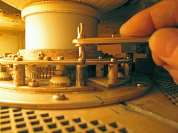
Fig. 6:
The best way to get the
socket geometry right is to
use a tube as an alignment
tool. Carefully tighten the
hardware as much as
possible, then remove the
tube and do the final
tightening. Recheck to make
sure the tube fits easily
into the socket. Inspect
fingerstock to see that it
equally depressed on all
sides of the tube. Sideward
pressure in only one
direction on a hot tube seal
is a formula for tube
disaster.
 |
|
Fig. 7:
Testing bypass
capacitors on the
bench.
|
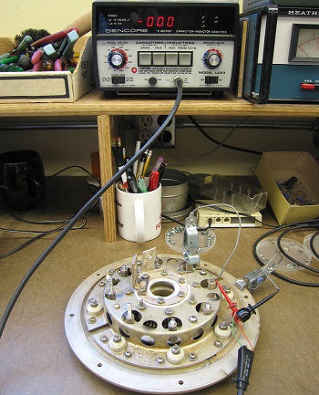
Fig. 7:
Here the socket insulators
and bypass capacitors are
being tested using a Sencore
Z Meter to see if there is
any leakage at 600 Volts.
This is the best time to
find a problem like that,
rather than after the socket
is back in the transmitter.
 |
| Fig. 8:
Installing a screen
grid ring in
transmitter.
|
Fig. 8:
Back in the transmitter, the
screen ring had to be
installed and tightened
after the rest of the socket
was in place. Again, a tube
was used as a jig to get the
alignment correct. A
right-angle screwdriver with
ratchet was ideal for final
assembly in this case. Note
the black permanent marker
line on the socket and
transmitter cavity. That
helped get parts back in the
original orientation. You
can get into real trouble in
a hurry if you don�t think
it all through first, and by
marking as you go.
If you run short on
hardware, use only copper,
brass or stainless steel in
an RF situation. If the
hardware sticks to a magnet,
it is ferromagnetic and will
tend to vibrate at the RF
frequency involved. This
could lead to the hardware
melting in the presence of
high power. I have seen it
happen. Some plastic or
nylon screws and nuts are OK
in RF and others are not. If
you hear a loud pop when RF
is turned on, then you will
know the hardware you used
was not RF compatible.
Take time to confirm that
all hardware is tight.
Cooling fan vibration can
easily loosen bolts and nuts
that were not snug at
installation time, resulting
in bad electrical
connections and erratic
transmitter operation. This
kind of project is not for
the faint of heart. Also, it
helps to have mechanical
skill. If you are the person
who has trouble deciding if
a square peg goes in a
square hole or in a round
hole, it is best to have
someone else help with the
tube socket mechanical work.
Don�t laugh; I have run into
otherwise great engineers
like that.
Double check the work and
use an ohmmeter to verify
there are no unwanted shorts
before turning power on.
Just think it through and
you should be fine.
Mark Persons, W0MH,
is a certified professional
broadcast engineer by the
Society of Broadcast
Engineers and has over 30
years of experience. He has
written numerous articles
for industry publications
over the years. His website
is
www.mwpersons.com.
|