|
Retired after 40 years in business |
 |
|
|
|
|
|
|||||||||
|
|
 |
||||||||
 |
Installing Connectors the
Right Way by Mark Persons |
Radio
World Article October 10, 2012 |
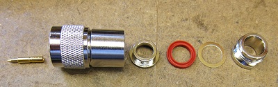
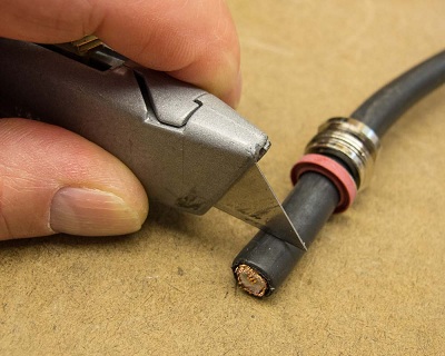
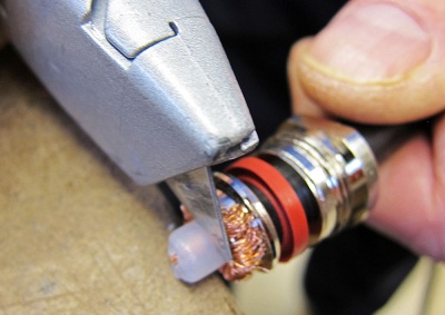
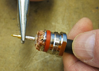
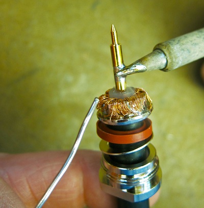
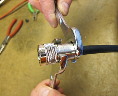
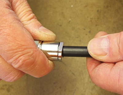
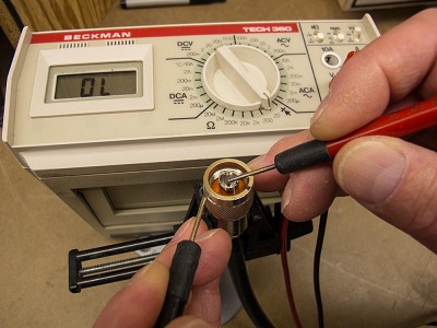
The work is not difficult. You just have to know how and it involves a little patience. Type N and BNC connectors are similar, but differ in size. Both are "coaxial," which means that there is an inner conductor and an outer shield. My preference is to solder with a clamp rather than crimp connectors. This may seem like the old-school method, but it is reliable. I remember receiving a factory-made cable that was crimped. When I picked it up I heard a clinking sound on the floor. A crimped center pin had fallen off. Right then, I knew that soldered connectors are much better. How-to Let's go through the installation procedure for type N male connectors with the plan to get good results. The most common cables are 50 ohm with a .405 inch (10.29 mm) outer jacket, such as RG-8, RG-213, RG-214, Belden 9913, Times Microwave LMR400 and other variants of this popular size. A good connector to use on these is the Amphenol 82-202-1006, available from many places, as well as Digi-Key, where the part number is ARF1020-ND. Start by cutting the end of the cable at 90 degrees. Cut it again if it is crooked. Open the connector package and remove the contents. Save the bag to the end in case you missed removing a part, such as the center pin. Slide the back nut, flat washer and rubber or plastic gasket washer over the end of the cable. Then use a box cutter tool to cut around the cable jacket about 5/16-inch back from the end. Try not to cut into the cable outer braid. Instead, score and then pull that end portion of the outer jacket away. Then slide on the clamp, sometimes called a tapered ring, followed by combing and pulling braid back over the outside of this clamp. The backside of the clamp should fit perfectly into a groove on the rubber washer. If not, the clamp is backwards. Trim braid wires if they want to go back past the clamp lip. Some engineers will solder the cable braid to the clamp, but tolerances are tight and it can be a tedious task involving filing down high parts so the connector fits together. I do not normally do that. Use the box cutter again to cut dielectric away from the center conductor about flush with the folded-over braid. Again, try not to damage the center conductor with the knife blade. Slide the center pin over the center conductor. If it fits loose, then remove the pin and use your soldering iron to "tin" the center conductor with some solder. Slide the pin back on and feed solder into the hole in the side of the pin. The plan is to have solder "suck" through the hole to bond the center conductor of the cable to the pin. If there is excess solder left over, use de-soldering braid to clean it up by pulling excess solder off the outside of the center pin. Use long-nose utility pliers to pull on the center pin to assure yourself that it is firmly in place and isn't going to fall off the center conductor. Eyeball the center pin in relation to the rest of the cable. Adjust its orientation as necessary to put it straight. Then slide the main body/front side of the connector on, pushing it until the tip of the center pin is flush with the end of the connector. This is very important. A pin that is too short may fail to make good contact and a pin that is too long could damage the receiving pin on the connector to which it ultimately is mated. In my case, I use 5/8-inch and 11/16-inch mechanics wrenches on the connector body and nut. The important part here is to turn the rear nut while holding the main body of the connector with the other wrench. You don't want to twist the main connector body on the cable as the action can shear off outer cable shield strands. When done right and tightened, the connector will be firmly attached to the cable. Test it by twisting the cable in one hand with the connector in the other hand. There should be no give. If there is movement you have done it incorrectly. The connector should be disassembled and installed again. A loose connector is trouble waiting for a time to show itself. Look at the end of the connector. Is the center pin in the exact center? If not, use a jeweler's screwdriver to align it before you try to plug it with any other connector. An off-center pin can damage the center-receiving pin on a mating connector. Use an ohmmeter to verify that the center pin on the connector gets to the other end of the cable and that it is not shorted to the shield by mistake. Take your time and avoid future problems now by doing it right. Type N connectors are available in 50 ohm and 75 ohm. The 75 ohm models have smaller inner pins. Do not interchange these; center pin damage may result, or there might be an intermittent connection. These are the most practical tips that I can pass on after building literally hundreds of cables over the years. Use them to get the job done right. Mark Persons W0MH is certified by the Society of Broadcast Engineers as a Professional Broadcast Engineer with over 30 years experience. He has written numerous articles for industry publications over the years. His website is www.mwpersons.com. This article also appeared in the online edition of Radio World on October 15, 2012. See: http://www.radioworld.com/article/installing-connectors-the-right-way/215926 November 12, 2012 e-mail: I read your Radio World article on proper installation of N connectors with interest. As a green engineer I remember the first time I opened the Amphenol and found no instructions. I started looking at the pile of parts and used deductive reasoning. (I was also a master at Erector sets in earlier years). Not sure how, but after a couple tries I got them in correct order and was pleased to see your detailed instructions matched what I have been doing for almost 40 years. Norm in Arlington, Texas. October 17, 2012 e-mail: Mark- Just read your great article in Radio World on putting N connectors on cable. Steve in San Francisco, California. October 16, 2012 e-mail: Hi Mark. I just read your "Installing Connectors the Right Way" tip article on the Radio World website. Very good, thank you. I too have fallen victim to poorly done connectors, typically high up on our tower where I can't get to them!! Mike in Kansas City, Missouri. October 12, 2012 e-mail: Another fine article about clamp N and BNC connectors in Radio World. Bob in Hamden Connecticut.
|
Mark Persons, W0MH, is certified by the Society of Broadcast Engineers as a Professional Broadcast Engineer and has more than 30 years experience. See you down the road. I'll leave the soldering
iron on for you. |
|
Questions? Email Mark Persons: teki@mwpersons.com |
|