| It all started when the phone rang.
A fairly savvy radio operations manager was at a site with a sick FM transmitter, a Continental 816R-2C 20 kW transmitter with a tube power amplifier, solid-state IPA (intermediate power amplifier) and 802B FM exciter.
The symptom: hours of normal operation would be interrupted when the RF output dropped suddenly to zero for a few seconds or a minute; then normal operation would resume.
During the episode the PA voltage would go up a bit while the PA current dropped to a low value. Screen current would be low as well. A VSWR light on the IPA would come on.
This gave every indication of an intermittent tube failure or capacitor failure in the PA tube socket. Changing the tube and visually checking capacitors yielded no results in fixing the intermittent.
When I arrived on the scene, I found that the exciter power would drop to zero for a few seconds and then return to normal. That happened at the beginning of each episode when the transmitter power output went to zero. The “mute” light on the exciter never came on, so I knew it wasn’t being told to turn off by the transmitter.
Don’t be a DIP
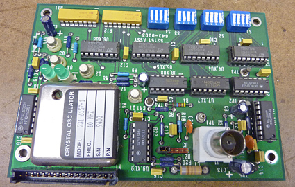 |
| The exciter’s audio/AFC card. |
|
Thinking through the problem, I connected a spectrum analyzer to an RF sample on a thru-line wattmeter section at the transmitter RF output port. All looked fine, with the analyzer showing the station’s carrier in the center of its screen.
When the transmitter power went to zero, there was no output from the transmitter at the station’s frequency. I expected to see a little of the exciter or IPA leaking through in the center of the display. Instead, I saw a new signal appear exactly 2 MHz up in frequency.
That was the clue I needed.
You remember that the exciter would drop to zero for a few seconds and then came back with normal power. Well, the exciter’s frequency synthesizer board is programmable via DIP switch. The 2 MHz switch was intermittent. It would open without warning, causing the exciter automatic frequency control to move the modulated oscillator to a new frequency and then turn RF back on.
When the exciter was on the wrong frequency, the IPA state driver would show VSWR to the power amplifier because the IPA to PA tuning was set for 2 MHz lower than the exciter was running at the time.
It all made perfect sense after the problem part was found and fixed.
In this case, I installed my loaner exciter and took the troubled exciter to the shop for repair.
Replacing just one DIP switch was not a good idea. Replacing all of the DIP switches in the exciter was the right idea. After all, if one failed, others could and probably would.
A photo shows the audio/AFC card from this exciter. Continental exciters are not the only ones that can exhibit this problem. Any piece of electronic equipment with DIP switches can suffer a similar fate. My rule of thumb is that if the switches have been in the equipment for more than 20 years, they are suspect and probably should be replaced.
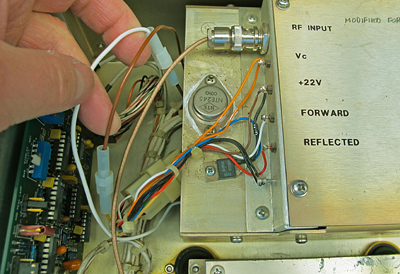 |
| The modification involves installing a 4 ohm/100 watt resistor under the heat sink. |
|
Regarding the Continental 802A and 802B FM exciters, there is a factory-recommended modification (200230-1) to improve the reliability of the exciter. This is for those who run their 50 watt exciter at less than 30 watts. It is somewhat common to have to replace replace the series-pass transistor in the exciter’s PA power supply. This transistor shorts, causing the exciter to put out full power. Ouch!
You see the transistor in Fig. 2 near the end of the PA heat sink assembly. It is an NTE245 NPN Darlington. That transistor is a TIP142 or an SJ3001 on some models. They fail because of heat as they regulate the 3 to 28 Volts DC PA power supply at up to 4 amperes of current.
The modification involves installing a 4 ohm/100 watt resistor under the heat sink. Wiring is reworked with quick couplers, shown here on white and brown wires, to connect or disconnect the resistor in series with the input to the transistor. When connected, the exciter is capable of producing only 30 watts of RF power. The transistor dissipates most of its heat when operating the exciter at under 30 watts of power so it shares the heat with the resistor when connected. |