|
(click thumbnail)
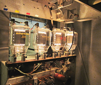
833A Tubes.
|
|
Many people
think old AM transmitters are
worthless.
If a
high-level, plate-modulated tube
transmitter is replaced by a shiny
new solid-state transmitter, why
should the old one be kept? Heck,
you might get $500 for the relic.
Well, I am
here to tell you that the new
whiz-bang transmitter should be
backed up by something that runs
when trouble strikes.
One station
owner told me the worst management
decision he ever made was to get rid
of his old transmitter after the new
one arrived. He paid for that
decision by being off the air for
three days.
Solid-state
transmitters need to see a 50-ohm
load with little reactance in order
to run properly. Old tube
transmitters can run into a “coat
hanger,” as many veteran engineers
would say. If the AM antenna is
misbehaving, a tube transmitter can
be your savior while antenna repairs
are made.
Most
transmitters sold today are touted
as being very reliable because a
power amplifier module can fail and
the transmitter will stay on the air
at reduced power. That is fine until
there is a logic problem, a power
supply problem, a driver problem, an
output network problem or some other
show-stopper.

|
|
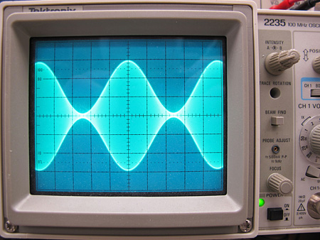
100% Modulation.
Tubes with good
emission give
low-distortion
results.
|
|
Having grown
up in a tube transmitter era, I
really appreciate the simplicity of
transmitters from the 1960s.
Probably the best example in my mind
is the Gates, now Harris, BC-1G. It
is a 1,000-watt transmitter using
833A tubes that really do glow in
the dark. One of my clients bought
two of these for use as backups for
his newly purchased solid-state
transmitters at two new AM stations
he constructed in recent years.
Warning!
If you decide to take on a project
like this, and if the transmitter
you are going to work on has
PCB-filled capacitors or PCB-filled
transformers, you really want to
replace them before turning the
power on. The same goes for mercury
vapor rectifier tubes. Anything else
in an old transmitter is harmless
except for the 2,500 or more volts
when the high voltage is turned on.
Sweat-reduction factor
The first part
of a transmitter rebuild project is
to test the transmitter and make
repairs necessary to get it running
to factory specifications on the
original frequency into a dummy
load. Be sure to spend some time
cleaning and replace any
questionable components that you can
spot with your eyes.

|
|
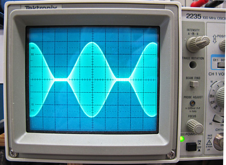
125% Modulation.
The audio is turned
up another 2 dB.
|
|
Most
transmitters from the 1950s through
the 1970s came with a tuning chart
in the instruction book. Capacitors
values are listed for every
frequency on the dial. Also shown is
the number of turns necessary on
each of the tuning coils for each
frequency, or group of frequencies.
If your
project involves changing frequency,
you will need a crystal for the RF
oscillator. Back then, they were
known as “fundamental” crystals that
oscillated at the frequency at which
the transmitter was intended to run.
Later transmitters used less
expensive crystals that were two or
four times the operating frequency
of the transmitter. That higher
frequency was divided down to the
final operating frequency.
Fundamental crystals are available
from International Crystal
www.icmfg.com for operation at 1
MHz and above, or from JAN crystal
www.jancrystals.com for any
channel on the AM band. You might
even find what you want at
commercialradiocompany.us.
I start a
tune-up at the crystal oscillator
before turning on the high voltage
at the lowest transmitter power
setting. Once things look right at
low power, I go to high power and
really make it sing.

|
(click thumbnail)
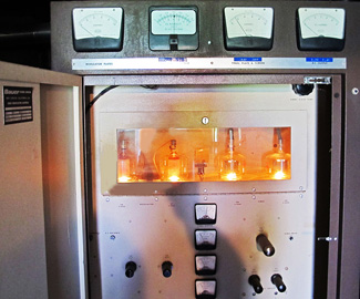
Bauer 707.
|
|
On AM
transmitters, there is more to
making them run than getting power
at carrier. I use an oscilloscope on
an RF sample port at the output of
the transmitter to watch the
modulated envelope when an audio
oscillator at 1 kHz is connected to
the audio input of the transmitter.
Tubes with
good emission give low-distortion
results as shown on the “100 percent
modulated photo.” Running regular
programming audio tells me almost
nothing about the audio performance
of a transmitter. Another photo
shows the audio turned up an
additional 2 dB. You see the carrier
go down to zero for an extended
period of time and the positive
peaks go up with the additional
audio. That is +125 percent positive
modulation.
If the
transmitter design is
less-than-great or the tubes are a
bit low on emission, you might have
to be satisfied with 100 percent
positive modulation. I write this
assuming the transmitter will be
used on the air only in emergencies.
Best to run
the old transmitter at least once
every three months. You will really
appreciate the value of a backup
transmitter the first time you use
it on the air. Sure, it is not as
energy efficient, but it will reduce
the sweat on your brow by a factor
of 100 when it is in on the air.
Mark
Persons, W0MH, is certified by the
Society of Broadcast Engineers as a
Professional Broadcast Engineer and
has more than 30 years experience.
His website is
www.mwpersons.com. |


