|
On a
nice sunny summer day in 2008 I was
doing annual, FCC-required National
Radio Systems Committee measurements
on WJON(AM) in St. Cloud, Minn.
The station had passed many
times, and there was no reason to
believe this time would be any
different.
Surprise, the NRSC test failed! We
encountered an RF mixing product at
1300 kHz. Things
became perfectly clear after a
moment. Just months before, KYES(AM)
on 1180 kHz had been built and
turned on.
|
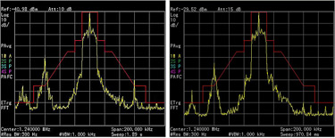
(click thumbnail)
Before-and-after
measurements using
an Agilent N9340B
spectrum analyzer.
|
|
The
two transmitter facilities are 15
miles apart. You would think that
wouldn’t present a problem, but it
did. KYES runs 50 kW with a
two-tower directional pattern
pointed at WJON. To make matters
worse, WJON is only a 1,000 watt
station on 1240 kHz but has a
five-eighths-wavelength tower, with
a gain of about 3 dB over a standard
quarter-wave tower. It makes a
wonderful receive antenna for 1180
kHz.
Yes,
this was a “perfect storm” to create
a problem. See the “before” photo of
the initial measurement using an
Agilent N9340B spectrum analyzer.
WJON is in the center and KYES is to
the left by just 60 kHz. A mix
product in the WJON transmitter,
between WJON and KYES at 1300 kHz,
is transmitted from the WJON tower
and peaks above the NRSC mask by 5
dB.
Ouch!
FCC Rule 73.44
(b) Emissions 10.2 kHz to 20 kHz
removed from the carrier must be
attenuated at least 25 dB below the
unmodulated carrier level, emissions
20 kHz to 30 kHz removed from the
carrier must be attenuated at least
35 dB below the unmodulated carrier
level, emissions 30 kHz to 60 kHz
removed from the carrier must be
attenuated at least [5 + 1 dB/kHz]
below the unmodulated carrier level,
and emissions between 60 kHz and 75
kHz of the carrier frequency must be
attenuated at least 65 dB below the
unmodulated carrier level. Emissions
removed by more than 75 kHz must be
attenuated at least 43 + 10 Log
(Power in watts) or80 dB below the
unmodulated carrier level, whichever
is the lesser attenuation, except
for transmitters having power less
than 158 watts, where the
attenuation must be at least 65 dB
below carrier level.
It is
clear WJON did not comply with the
rules. Some would say KYES was the
cause and should have been required
to fix the problem at WJON. Others
would disagree.
No
matter how you look at it, WJON
ultimately is responsible for
maintaining compliance with FCC
rules at its transmitter plant, or
risk losing its license.
For
those who are unfamiliar with this
kind of problem, the transmitter is
almost always where mixing of
signals takes place. This is a
well-known phenomenon. Each
transmitter has its own “turn-around
loss” in its power amplifier where
the mix occurs. The good part is
that KYES did not induce enough RF
current to make the WJON antenna
current meter read above zero.

|
(click thumbnail)
The station hired
Kintronic Labs to
design a filter to
nudge WJON into
compliance with FCC
rules.
|
|
What to do
The
station hired Kintronic Labs to
design a filter to nudge WJON into
compliance with FCC rules. Kintronic
came back with a design to put a
1240 kHz pass/1180 kHz reject filter
on the 50 ohm side of the WJON
antenna coupling network. There was
no attempt to filter 1300 kHz. The
idea was to attenuate 1180 kHz by at
least 10 dB to reduce the mixing
that results in a 1300 kHz spur.
The
filter is a fixed vacuum capacitor
with tapped coil in series to
pull/trap 1180 kHz to ground. A
variable vacuum capacitor in
parallel with the series trap is
used to parallel resonate the
arrangement to 1240 kHz. This makes
the network a nearly infinite
resistance at 1240 kHz with very
little degradation even at 1230 and
1250 kHz.
WJON
Engineer Mark Young built an
aluminum box under the existing
antenna coupling network inside the
shack at the base of the WJON tower.
He cut a hole between the two boxes
to allow a single copper tube
through. This connected to the
incoming 50 ohm transmission line
via a J-jack and J-plug. The
arrangement made it possible to tune
and test the network without taking
the transmitter off the air except
for installation of the J-jack.
In the end
The
filter worked as expected. You can
see the result in the “after”
display of the spectrum analyzer.
This
goes to show that you never know
what might happen from year to year
at a transmitter site. I uncover a
problem or two every year when doing
NRSC measurements for AM clients.
Yes,
annual measurements are not required
on FM stations, but these kinds of
measurements should be made on a
regular basis just to confirm
compliance with FCC rules. Mixing
can and does occur in FM
transmitters as well.
Mark Persons W0MH is certified by
the Society of Broadcast Engineers
as a Professional Broadcast Engineer
and has more than 30 years’
experience. He has written numerous
articles for industry publications
over the years. His website is
www.mwpersons.com. |